|
|
This task illustrates how to create a Multi-Axis Flank Contouring
operation in the program. The tool axis will be guided in
Tanto Fan mode. To create the operation you must define:
|
|||||
|
|
Open the Flank_5X_test_part.CATPart
document, then select Machining > Advanced Machining
from the Start menu. Make the Manufacturing Program
current in the specification tree. |
|||||
|
|
1. |
Select the Multi-Axis Flank Contouring icon
A Multi-Axis Flank Contouring entity along with a default tool is added to the program.
|
|
|||
|
|
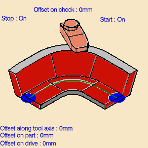
The part, drive and start/stop elements of the sensitive icon are colored red indicating that this geometry is required. | |||||
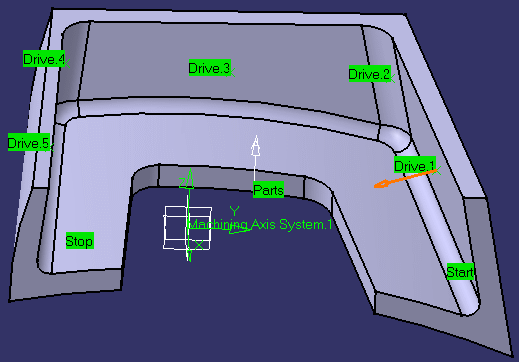
| 2. | Click the red part surface in the icon then select the desired surfaces in the 3D window. | |||||
| 3. | Click the red drive surface in the icon then select the desired drives in the 3D window (Drives 1 to 5). | |||||
| 4. | Click the start and stop elements in the icon then select the desired limiting elements in the 3D window. | |||||
|
|
||||||
|
|
After geometry selection, the surfaces of the icon are colored green indicating that this geometry is now defined. | |||||
| 5. |
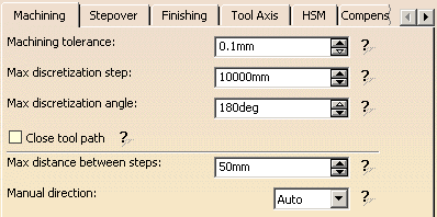
Select the Strategy tab page
In this example, Finishing, High-speed milling and Compensation are not required. |
|||||
| 6. |
Click Preview in the dialog
box to verify the parameters that you have specified. A message box appears giving feedback about this verification. |
|||||
| 7. |
Select the Tool tab page
For more information please refer to Edit the Tool of an Operation. |
|||||
| 8. |
If needed, select the Feeds and Speeds
tab page
|
|||||
| 9. |
If needed, select the Macros tab page
|
|||||
| 10. |
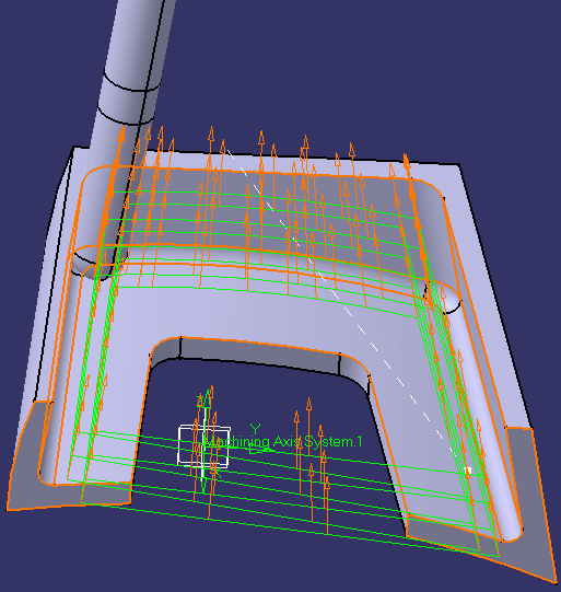
Before accepting the operation, you should check its validity
by
replaying the tool path.
|
|||||
| 11. | Click OK to create the operation. | |||||
|
|
|
|||||
|
|
||||||


