Using the graPHIGS API programming tools enables your application to assemble a graphics model. The assembled graphics model is defined in a system of coordinates known as the World Coordinate System (WCS). The viewing subroutine calls provided by the graPHIGS API enable your application to define what part of the WCS is visible. They also help to simulate various camera-like operations such as flying through space, panning, and zooming.
In order to establish what part of the WCS is visible, your application must define a view. Defining a view involves specifying its:
The graPHIGS API lets your application define and modify viewing parameters. Calling a viewing subroutine sets the requested viewing entries in a workstation's view table. When a workstation is updated, the requested values become the current values. Updating the workstation is discussed in Chapter 6. "Displaying Structures"
Views are stored in a view table as part of the WSL. The number of entries in the view table may vary for each workstation and is defined in the WDT. All the view table entries of the WSL are initialized to default values. These values are explained in the The graPHIGS Programming Interface: Technical Reference Your application may modify any entry in a view table except view zero.
In the sample program introduced in Chapter 1, the following statements defined the viewing parameters for view index 1 of the workstation view table:
     CALL GPXVR(WSID,VIEW1,14,VIEWPT)
     CALL GPXVR(WSID,VIEW1,16,WINDOW)
     CALL GPXVCH(WSID,VIEW1,1,8,2)
The first two statements define the window and viewport and the next statement the view characteristics. The view matrix used is the default matrix. The priority of this view is not modified.
The following sections discuss ways to modify viewing parameters and the effects of modifying entries in a workstation's view table.
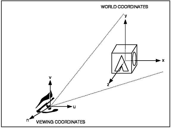
In order to establish a view, other than the system's predefined view, you must specify a viewing transformation matrix. This matrix establishes a Viewing Coordinate System (VCS).
Initially, the system's predefined view places the VCS coincident with the WCS. The figure, "Relationship between the WCS and the VCS," depicts the relationship between the World Coordinate System and the Viewing Coordinate System.
The Viewing Coordinate System serves as a frame of reference for the viewer. With this frame of reference, your application can define the viewer's field of vision as discussed in "Window and Viewport Definition"
Your application can use the default viewing transformation matrix. The default establishes the origin of the VCS at the origin of the WCS, and aligns the N and V axes in the VCS with the Z and Y axes in the WCS, respectively.
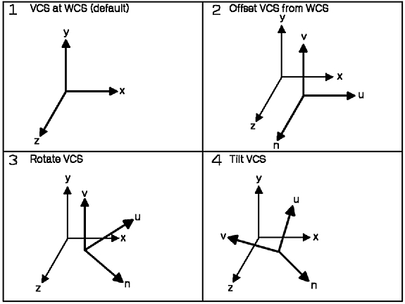
The figure, "How the Viewer's Field of Vision Follows the Changes Made to the VCS," depicts how the viewer's field of vision follows changes made to the VCS.
The Set Extended View Representation (GPXVR) subroutine enables your application to set different fields in the workstation view table entry.
By setting specific parameters of the GPXVR subroutine, your application can assign two- or three-dimensional transformation matrixes to entries in a workstation's view table. The definition of the viewing matrix is applied when the API displays the root structures associated with that view.
Other aspects of defining a view are discussed in the following sections of this chapter. Displaying a view and its contents is discussed in Chapter 6. "Displaying Structures"
This section discusses the programming subroutine calls that enable your application to define:
The Set Extended View Representation (GPXVR) subroutine will also give your application the ability to provide the above viewport and window definitions for two- or three-dimensional viewing.
The following sections discuss how each aspect of the window and viewport definition contributes to the viewing environment.
Notice that your application has the option of using the system's default values for window boundary, type of viewing, and viewport mapping specifications. Refer to The graPHIGS Programming Interface: Subroutine Reference for further details.
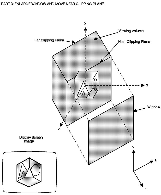
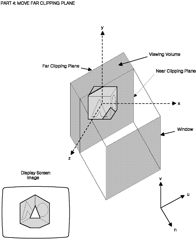
The graPHIGS API provides parameters in the GPXVR subroutine that let your application define the clipping boundaries of a two- or three-dimensional field of vision. In order to define clipping boundaries, your application specifies, within the VCS:
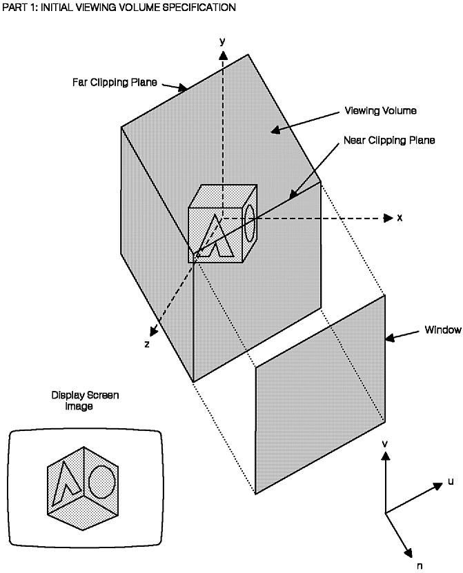
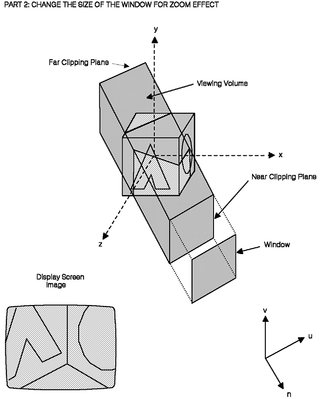
The figures, "Modifying the Viewing Volume (Projection = Parallel) (Part 1 of 4)," "(Part 2 of 4)," "(Part 3 of 4)," and "(Part 4 of 4)," depict how changes to the viewing volume can zoom in on and clip the front or back of the model. Notice that the projection type in these figures is parallel and that the viewport remains consistent throughout.
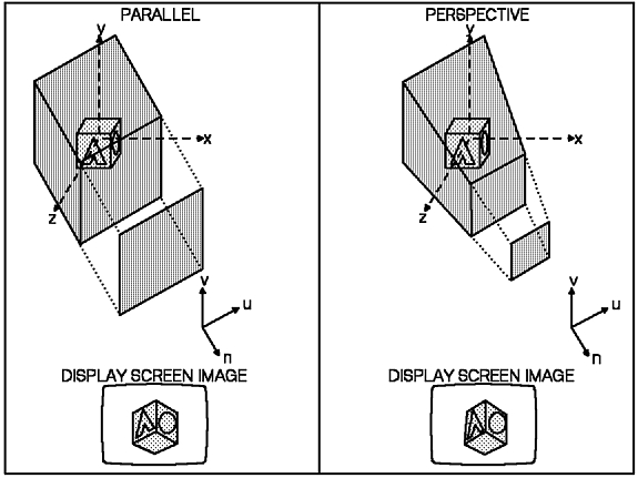
For three-dimensional viewing the graPHIGS API provides a parameter in the GPXVR subroutine that enables your application to request two viewing orientations:
The figure, "How Parallel and Perspective Viewing Affects Viewing Volumes and Images," depicts how parallel and perspective viewing affect the viewing volume and the image of a cube.
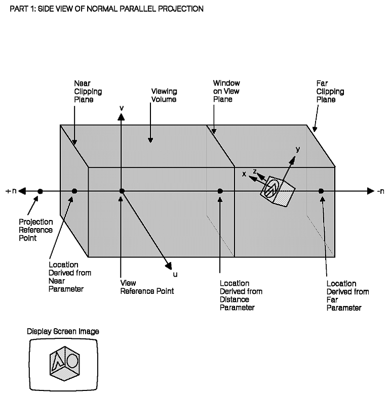
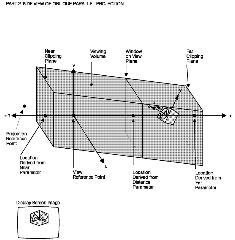
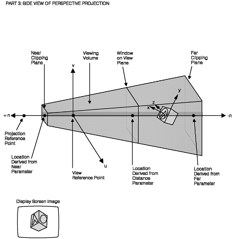
The figures, "Sample Placements of View Mapping Parameters (Part 1 of 3)," "(Part 2 of 3)," and "(Part 3 of 3)," depict three side-views of typical window, view reference point, and projection reference point placements. The projection reference point is used in conjunction with the center of the window to define the direction of projection. For PARALLEL projection, all projectors are parallel to the line defined by the projection reference point and the center of the window. For PERSPECTIVE projection, all projectors converge on the projection reference point. The viewer's field of vision is defined by those converging lines that pass through the window and are within the near and far clipping planes. The first part shows PARALLEL projection. The second part shows PERSPECTIVE projection. Each part also shows the resulting display screen image.
The graPHIGS API provides a parameter in the GPXVR subroutine that lets your application control where to position the view. The system maps the view to a viewport in a logical workstation space called normalized projection coordinates (NPC). NPC is defined as a cubic space ranging from zero to one along each axis.
Your application specifies the boundaries of a two- or three-dimensional viewport in NPC. This viewport serves as a destination for the view in NPC.
NPC is a workstation-dependent, device-independent space in which to specify a logical viewport. Creating a logical viewport gives different devices a common set of values from which to base a mapping to their actual screen.
The next mapping, by default, maps all of NPC onto the entire workstation viewport. This mapping may be modified and is discussed in "Mapping of NPC to Output Devices". The figure, "Staged Representation of Viewing Process," depicts the stages involved in the viewing process from the creation of a VCS in the WCS to the viewport mapping into NPC.
A one-to-one correspondence exists between a view and a viewport. The following two sections: "View Priority" and "View Characteristics" show you how to control the appearance of viewports and their relation to other viewports on a display surface.
The Set View Output Priority (GPVOP) subroutine lets your application specify a view's output priority relative to another view. This determines the order in which the system presents each view on the output device. Higher priority views are drawn last so they overlay the lower priority views.
The Set View Input Priority (GPVIP) subroutine is similar to GPVOP, but sets a view's relative input priority for LOCATOR , STROKE , and extended PICK input. To set the view input and view output priorities at the same time, your application should issue a Set View Priority (GPVP ) subroutine. Mixing different view input and output priorities is discussed in detail in Chapter 15. "Advanced Viewing Capabilities" in Part Two of this book.
When a workstation is opened, its view zero has the highest input and output priority. Notice that this ordering is not static. The graPHIGS API supports dynamic modification of view priorities.
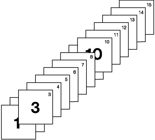
The figure, "Controlling View Priorities," depicts various changes to the view output priorities of fifteen viewports. In the figure, the application gave view 3 a higher priority than view 1 (which has a higher output priority than view 2). Also, the application gave view 9 a lower output priority than view 10.
The graPHIGS API gives your application control over a viewport's appearance on a display. The Set Extended View Characteristics (GPXVCH) subroutine lets your application:
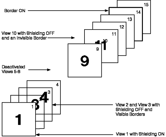
You should know that the graPHIGS API does not process the content associated with inactive views, although the view's content is still defined to the workstation. The shielding characteristic controls the transparency of the view. When the Shielding Indicator is ON the view background is filled and it shields the content of all lower priority views behind the extents of that viewport. The figure, "Controlling View Characteristics," depicts how these controls affect the appearance of views.
Window clipping, near clipping, and far clipping may each individually be turned ON or OFF. When your application disables any of these clipping boundaries, the API performs clipping to the workstation which is described in the next section. This remains in effect unless your application modifies the relationship between NPC space and the display surface as part of the workstation transformation discussed in "Mapping of NPC to Output Devices" Also, if window clipping is turned OFF , the data in that view may extend beyond its corresponding viewport boundaries, and may overlap data in other views. Nevertheless, in this case, the same viewport shielding remains in effect.
When set to ON, the temporary view indicator identifies to the workstation support software that the corresponding view will have its view activity changed frequently. When the corresponding temporary view is activated the image of the underlying screen is saved by the device. When it is deactivated the underlying screen image is restored without requiring structure traversal. A typical application of the temporary view capability is the "pop-up-menu"
Extended view characteristics associated with advanced viewing concepts are discussed in detail in Chapter 15. "Advanced Viewing Capabilities"
The previous sections explained how to create logical viewports in NPC space. This section explains how to control the mapping of NPC space to the physical device.
The process of mapping NPC space to a device is called the workstation transformation. The Set Workstation Transformation (GPWSX2 and GPWSX3) subroutine enable your application to specify the workstation transformation. This isotropic mapping is device-dependent and results in a representation of the model in Device Coordinate (DC) space.
By default, the system provides the most trivial and useful mapping. It maps the entire NPC space onto the largest usable portion of the workstation's DC space.
For example, your application might choose to map the entire NPC space (0,0,0 to 1,1,1 in the window parameter of the GPWSX3 subroutine) to the entire display screen of an output device such as in the IBM 5080 Graphics System with a DC space from 0 meters to .28448 meters.
For devices with a square screen, this results in the mapping of all NPC onto the entire display surface. Typically, applications do not need to modify this relationship. One reason to modify the workstation transformation is to utilize the entire display surface of a workstation with a rectangular display surface, such as an IBM GDDM device.
Your application can determine the extents of a workstation's DC space using the Inquire Maximum Display Surface Size (GPQDS) subroutine. See the discussion of workstation related inquiries in Chapter 9. "Inquiry Subroutines", for more information on the use of inquiries.
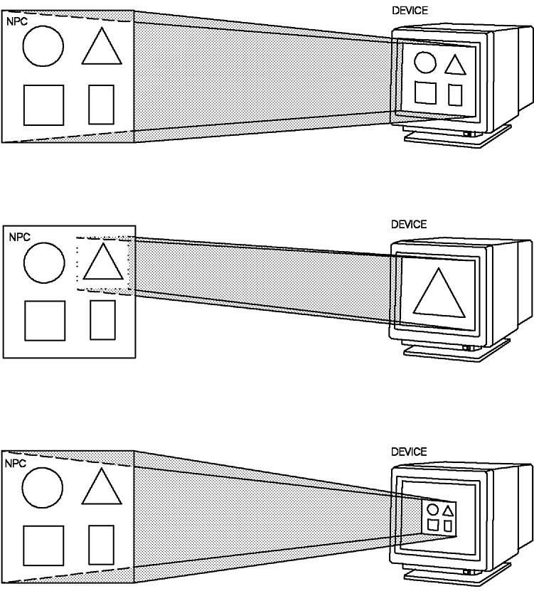
The graPHIGS API also supports more advanced uses of the workstation transformation. Your application can choose to map any part of the NPC space (GPWSX2 or GPWSX3 workstation window parameter) to any supported part of DC space (workstation viewport) on the particular output device. Notice that during a workstation transformation the API maintains the same aspect ratio in the workstation viewport that existed in the workstation window, as shown in the figure, "The Result of Various Workstation Transformations."
| Modified Sample Program 1 |
|---|
Make the following changes to the house program for a better understanding of view mapping. (See pages Sample Program, Sample Program, and Sample Program). You will add a new view definition and modify the old one.
|
Make the changes in your sample program, compile and run it. The display should show two views of the house, as shown in the figure, "Two views of the house." By introducing the changes explained you have modified the view parameters for view index 1 and 2 of the workstation view table.
View 2 is located in the top righthand corner, and view 1 in the lower lefthand corner. The same structure is associated to both views. You will learn about association of structures to views in the next chapter.
The difference in size of the houses in each view is due to the window size used. This is a zoom effect. View 1 has a larger window size than view 2, therefore the house in view 1 is smaller. Other methods for zoom effects use the view transformation matrix.
View 2 has the border indicator on, and the border color is white, no shielding is in effect. View 1 has no border and no shielding. Priorities have not been modified. The view matrix used is the default view matrix.