This chapter contains the following sections:
Certain capabilities are available only on specific workstations. Therefore, your application should use the inquiry subroutines discussed throughout this chapter to make your application portable to other hardware platforms.
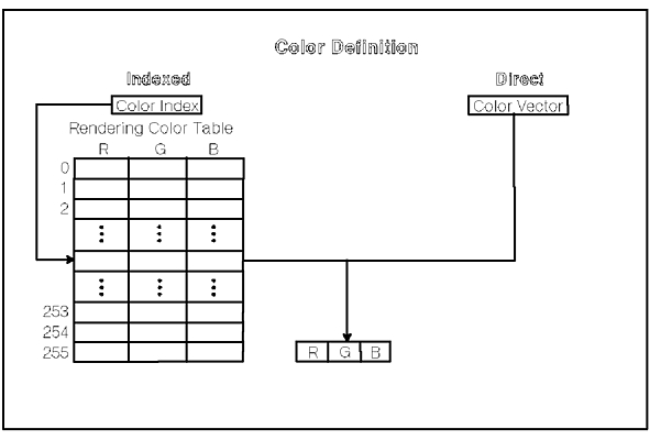
There are two ways to specify colors in the graPHIGS API: indexed and direct. When using indexed color, your application defines colors as indexes into a workstation's rendering color table. Each entry in a rendering color table is a color vector which can be set using the Set Extended Color Representation (GPXCR) subroutine. A color vector is defined as three floating-point numbers ranging from zero (0.0) to one (1.0), representing color components in the current workstation color model. Use the Set Color Model (GPCML) subroutine to set the workstation's color model. The supported color models are:
By setting the color model, your application can specify color values relative to the desired color model. Since most workstations use only one color model (usually the RGB color model), colors are automatically converted from the values of the color model, specified in the GPCML call, to the workstation's real color model.
When converting CIELUV color components to another color model (typically RGB), the CIELUV values are clipped at a constant luminence to create valid RGB values. If your application specifies CIELUV values that are clipped, inquiring the color value will return the CIELUV values of the RGB color created by the conversion clipping.
The second way to define colors is to bypass the rendering color table by specifying colors directly as color vectors. Direct color vectors are interpreted according to the current Direct Color Model and can be set using the Set Direct Color Model (GPDCM) subroutine. The direct color model can be RGB , HSV , CMY , or CIELUV , and only effects direct color setting structure elements such as Set Polyline Color Direct.
The color definition phase is summarized in the figure, "Color Definition Phase." The result of this phase is a color vector which is passed to the rendering pipeline.
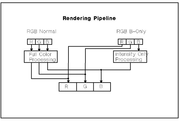
The input to the rendering pipeline is a color vector. This vector is processed by the rendering pipeline as described in Chapter 16. "Rendering Pipeline" The rendering pipeline processes color according to the rendering color model in the current color processing table entry. The Rendering Color Model can be 1=RGB_NORMAL or 2=RGB_B_ONLY In the 1=RGB_NORMAL model, all three components of the color are manipulated by the rendering pipeline. In the 2=RGB_B_ONLY model, only the blue component is manipulated by the rendering pipeline. The red and green components pass through the rendering pipeline unchanged. An example of how 2=RGB_B_ONLY model is used is presented in "Color Processing Examples"
A color processing table entry can be selected using the Set Color Processing Index (GPCPI) subroutine. A color processing table entry contains the color processing model (1=RGB_NORMAL or 2=RGB_B_ONLY ), quantization method, and quantization parameters. Color quantization is discussed in the next section.
All workstations have a color processing table with at least one entry, entry zero, which contains the default color processing information and cannot be changed. To set a color processing table entry your application can call the Set Color Processing Representation (GPCPR) subroutine. To determine the color processing capabilities of a workstation, your application should use the Inquire Color Processing Facilities (GPQCPF) subroutine.
See the figure, "Rendering Color Models."
Color quantization is defined as the process or method of mapping a specified color to a displayable color on the target workstation. For the graPHIGS API, the Quantization Method currently defined is BITWISE quantization.
Note: Some workstations have limited color resolution. That is, they are limited in the number of colors they can display at any one time. Shaded images, for example, can appear faceted on a workstation with limited resolution. An alternative is the use of a technique called dithering to improve the image output quality. For some workstations with limited color resolution, dithering is always on.
BITWISE quantization involves the following set of color quantization parameters:
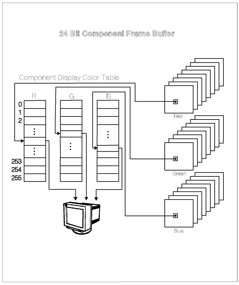
The use of these parameters depends on the type of frame buffer used by the workstation. There are two types of frame buffers: component and indexed. A component frame buffer consists of three conceptually separate color component buffers; one each for red, green, and blue as shown in the figure, "24 Bit Component Frame Buffer." Each component of the buffer contains a color value for each pixel on the display surface. The color value represents an index into the workstation's display color table as shown in the figure, "24 Bit Component Frame Buffer."
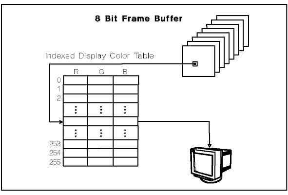
An indexed frame buffer contains only one display color table index for each pixel on the display surface as shown in the figure, "8-Bit Indexed Frame Buffer," as opposed to the three color indexes provided by a component buffer.
Component frame buffers provide millions more simultaneously displayable colors than do indexed frame buffers due to the separate indexing of the red, green, and blue components. For example, a workstation with a display color table of 256 entries and a component frame buffer with a bit depth of 24 bits (8 bits for each color component) will be capable of displaying from a palette of 16.7 million colors simultaneously. The same workstation would only be able to display 256 colors simultaneously using an index frame buffer.
Note that not all workstations support a display color table with 256 entries and some do not have user-definable display color tables. Therefore, to determine whether or not a workstation's display color table is modifiable, your application should call the Inquire Extended Color Facilities (GPQXCF) subroutine. For workstations which do have a modifiable display color table, your application can inquire the size of the table using the Inquire Color Table Characteristics (GPQCCH) subroutine. Your application can determine a workstation's frame buffer type and depth by calling the Inquire Frame Buffer Characteristics (GPQFBC) subroutine.
If the workstation has a component frame buffer, color quantization is performed on each red, green, and blue color component independently. Each color component is converted from a floating-point number between 0.0 and 1.0 to an N bit unsigned integer in the range 0 to 2Nx - 1 where Nx is the number of red, green, and blue bits (Nr, Ng, Nb) to be used in the final color value. The remainder of the bits are filled with the corresponding padding bits as shown in the figure, "Color Quantization for a Component Frame Buffer."
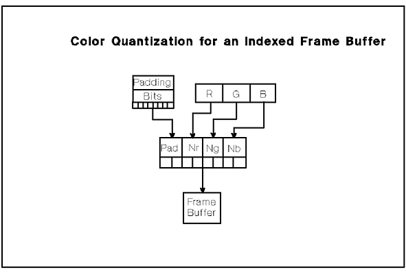
If the workstation has an indexed frame buffer, the BITWISE Quantization Method is used to reduce the RGB color vector down to a N bit integer where N is the bit depth of the frame buffer. Your application can determine the bit depth of an indexed frame buffer using the GPQFBC subroutine.
Color quantization for an indexed frame buffer is performed as follows:
The N bits of data are then written to the frame buffer as an integer index into the workstation's display color table.
Note that on some workstations, the ordering of the Nr and Nb bits within the quantized color value is reversed, resulting in BGR color quantization instead of RGB color quantization. The reversing of the red and blue bits affects how colors are quantized, including colors taken from the rendering color table. An upcoming example in this chapter (the figure, "Initializing the default color table with a BGR color ramp") illustrates how to set up a BGR rendering color table ramp for the 8-bit 3D Color Graphics Processor available for the RISC System/6000. Your application can determine whether a workstation performs BGR or RGB quantization through the Inquire List of Color Facilities (GPQLCF) subroutine.
Initializing the default color table with a BGR color rampTo maintain upward compatibility with Version 1 of the graPHIGS API, all workstations by default process colors in a way similar to an IBM 5080. This means that to perform lighting, shading, depth cueing and direct color processing correctly, a workstation's color tables and color processing modes will have to be modified. Modifying the way a workstation processes colors is discussed in "Color Processing Examples". The following sections discuss how individual workstation configurations process color by default.
To improve performance and speed in processing direct colors, a workstation PROCOPT can be set that causes a workstation to initialize the display color table differently. If the DIRCOLOR PROCOPT is specified, the workstation will initialize the color table components using values that range uniformly from the minimum component value to the maximum component value (linear ramps of the color components).
All of the various GDDM devices have a predefined display color table with either 8 or 16 entries. Because the entries in the display color table are fixed, your application can only change the contents of the rendering color table using either the Set Color Representation (GPCR) or the Set Extended Color Representation (GPXCR) subroutines. The colors entered into the rendering color table and direct colors specified by your application are mapped automatically to the closest approximation in the display color table using a 1=WORKSTATION_DEPENDENT Quantization Method. This means that the use of direct color will work without having to change the default configuration.
All of the various 5080 models have an indexed frame buffer that is up to 8 bits deep. One of the bits is reserved by the graPHIGS API for input device echoes and prompts, leaving up to 7 available bits for use by your application. The actual number of available bits can be inquired using the Inquire Frame Buffer Characteristics (GPQFBC) subroutine.
By default, a 5080 workstation with 7 available frame buffer bit planes has a display color table with 128 entries and a rendering color table with 256 entries. The default Color Quantization Method is BITWISE 2-3-2-0 which means that 2 bits of red, 3 of green, 2 of blue, and no padding bits are used to quantize color vectors into 7 bit color indexes.
By default, the display color table is loaded as follows:
| Index | Color (R,G,B) |
| 0 | Black (0.0, 0.0, 0.0) |
| 1 | White (1.0, 1.0, 1.0) |
| 2 | Red (1.0, 0.0, 0.0) |
| 3 | Green (0.0, 1.0, 0.0) |
| 4 | Blue (0.0, 0.0, 1.0) |
| 5 | Yellow (1.0, 1.0, 0.0) |
| 6 | Magenta (1.0, 0.0, 1.0) |
| 7 | Cyan (0.0, 1.0, 1.0) |
| 8-127 | White (1.0, 1.0, 1.0) |
The rendering color table is loaded to produce a one-to-one mapping between the rendering color table and display color table. For example, entry 5 in the rendering color table contains the color vector (0.000, 0.143, 0.333) which when quantized using 2-3-2-0 quantization will produce the integer index 5. So, a 2-3-2-0 color table in combination with 2-3-2-0 color quantization produces the indexes 0 thru 127 for the rendering color table entries 0 thru 127. By default, entries 128 through 255 in the rendering color table map to index 1 in the display color table.
The default Rendering Color Model for a 5080 workstation is 1=RGB_NORMAL
The Base 6090 without the Extended Pixel Memory (EPM) feature, has an indexed frame buffer that is 8 bits deep and therefore has a display color table with 256 entries. The default Color Quantization Method is BITWISE 3-3-2-0. 3-3-2-0 quantization means that 3 bits of red, 3 of green, 2 of blue, and no padding bits are used to quantize color vectors into 8-bit color indexes.
By default the display color table is loaded as follows:
| Index | Color (R,G,B) |
| 0 | Black (0.0, 0.0, 0.0) |
| 1 | White (1.0, 1.0, 1.0) |
| 2 | Red (1.0, 0.0, 0.0) |
| 3 | Green (0.0, 1.0, 0.0) |
| 4 | Blue (0.0, 0.0, 1.0) |
| 5 | Yellow (1.0, 1.0, 0.0) |
| 6 | Magenta (1.0, 0.0, 1.0) |
| 7 | Cyan (0.0, 1.0, 1.0) |
| 8-255 | White (1.0, 1.0, 1.0) |
The default color processing model is RGB_NORMAL and the input color table by default is loaded such that each input color table entry maps to the corresponding output color table entry. This is accomplished by loading entries 0 thru 255 with a 3-3-2-0 color table. A 3-3-2-0 color table in combination with 3-3-2-0 color quantization produces the indexes 0 thru 255 for rendering color table entries 0 thru 255.
When equipped with the Extended Pixel Memory (EPM) feature, the 6090 has a component frame buffer that is 24 bits deep. Like the base 6090, a 6090 with EPM has a display color table with 256 entries but the default Color Quantization Method set to BITWISE 8-8-8-0. 8-8-8-0 quantization means that color values are quantized such that each component of the frame buffer will receive an index into the display color table. By default, the display color table is loaded with the same values as a base 6090.
As with the base 6090, the default color processing model is RGB_NORMAL and the input color table by default is loaded such that each input color table entry maps to the corresponding output color table entry.
In some cases you may wish to modify the way a workstation processes colors. For example, you may wish to define a range of colors for shading objects and another range to be used for the display of menus and other screen colors. In general, the default color processing configuration of a workstation will not be sufficient to handle shading and the use of direct color. The remainder of this chapter addresses a few of the typical color processing scenarios you may face when developing a graPHIGS API application. The scenarios are organized based on the following hardware configurations the graPHIGS API currently supports:
As discussed in the previous section, a GDDM device, such as a 3279 terminal, is limited to a maximum of 16 predefined colors in the display color table. To provide direct color support on a GDDM type device, the graPHIGS API maps color vectors to the closest available color using a 1=WORKSTATION_DEPENDENT Color Quantization Method. No other quantization methods are supported. The color vectors are taken either from the rendering color table when color indexes are used or directly when direct color vectors are supplied by your application. Therefore, your application does not need to perform any special processing in order to use the direct color support provided by the graPHIGS API on GDDM type devices.
The various models of the 5080 support only indexed frame buffers of up to 8 bits per pixel. The actual number of bits can be inquired using the Inquire Frame Buffer Characteristics (GPQFBC) subroutine. The graPHIGS API reserves one of the bit planes for input device echoing and prompts leaving up to 7 bits for your use. To use direct color on a 5080 your application must redefine the 5080's display color table to match the default color quantization method used for the workstation. For example, the default color quantization method used for a 5080 with 7 available bit planes is 2-3-2-0 quantization. 2-3-2-0 quantization means that 2 bits of red, 3 of green, 2 of blue, and no padding bits are used to quantize a direct color vector into a 7 bit display color table index. The FORTRAN subroutines shown in the figures, "Initializing a display color table for direct color processing," "Calculating color table entries for an index frame buffer," and "Calculating color table entries for a component frame buffer," show how a display color table can be initialized to make use of direct color. The subroutines perform the necessary inquires to determine the type and size of the workstation's frame buffer in order to initialize the display color table correctly.
Figure: Initializing a display color table for direct color
processing.
| Example Subroutine |
|---|
**********************************************************************
*                              S E T C T
**********************************************************************
*   FUNCTION:  INITIALIZES A WORKSTATION'S DISPLAY COLOR TABLE
*              BASED ON THE NUMBER OF AVAILABLE BIT PLANES IN
*              THE WORKSTATION'S FRAME BUFFER.
**********************************************************************
*  CALLED BY:  APPLICATION PROGRAM
**********************************************************************
* PARAMETERS:  (INPUT)
*   INTEGER WSID - WORKSTATION IDENTIFIER
**********************************************************************
* PARAMETERS:  (OUTPUT)
*   NONE
**********************************************************************

      SUBROUTINE SETCT(WSID)

      INTEGER WSID
      REAL    COLOR(3, 256)
      INTEGER ERRIND, ORG, N, DEPTH(3), CIDLEN
      CHARACTER*8 CONNID, WSTYPE
      INTEGER CTID, START, CTSIZE
      PARAMETER (CTID = -1, START = 0)

C     INQUIRE REALIZE CONNECTION AND TYPE
      CALL GPQRCT(WSID, LEN(CONNID), ERRIND, CIDLEN, CONNID, WSTYPE)

      IF (ERRIND .EQ. 0) THEN
C       INQUIRE FRAME BUFFER CHARACTERISTICS
        CALL GPQFBC(WSTYPE, ERRIND, ORG, N, DEPTH)
        IF (ERRIND .EQ. 0) THEN
          IF (N .EQ. 1) THEN
C           CALCULATE COLOR TABLE VALUES FOR INDEXED FRAME BUFFER
            CALL GETCTI(DEPTH, CTSIZE, COLOR)
          ELSE IF (N .EQ. 3) THEN
C           CALCULATE COLOR TABLE VALUES FOR COMPONENT FRAME BUFFER
            CALL GETCTC(DEPTH, CTSIZE, COLOR)
          ELSE
C           SOMETHING IS WRONG
            WRITE(*,*)'NUMBER OF FRAME BUFFER COMPONENTS NOT 1 OR 3'
            RETURN
          ENDIF
        ELSE
C         GPQFBC FAILED SO ISSUE ERROR
          WRITE(*,*)'ERROR RETURNED BY GPQFBC (ERRIND = ',ERRIND,')'
          RETURN
        ENDIF
      ELSE
C       GPQRCT FAILED SO ISSUE ERROR
        WRITE(*,*)'ERROR RETURNED BY GPQRCT (ERRIND = ',ERRIND,')'
        RETURN
      ENDIF

C     SET COLOR TABLE
      CALL GPXCR(WSID, CTID, START, CTSIZE, COLOR)

      RETURN
      END
|
Figure: Calculating color table entries for an index frame
buffer.
| Example Subroutine |
|---|
**********************************************************************
*                            G E T C T I
**********************************************************************
*   FUNCTION:  CALCULATES COLOR TABLE VALUES BASED ON THE NUMBER OF
*              AVAILABLE BIT PLANES IN A WORKSTATION'S INDEXED FRAME
*              BUFFER.
**********************************************************************
*  CALLED BY:  SETCT - SET COLOR TABLE
**********************************************************************
* PARAMETERS:  (INPUT)
*   INTEGER DEPTH      - BIT DEPTH OF INDEXED FRAME BUFFER
**********************************************************************
* PARAMETERS:  (OUTPUT)
*   INTEGER CTSIZE     - SIZE OF THE COLOR TABLE
*   REAL    COLOR(3,*) - COLOR TABLE VALUES
**********************************************************************

      SUBROUTINE GETCTI(DEPTH, CTSIZE, COLOR)

      INTEGER DEPTH, CTSIZE
      REAL    COLOR(3,*)
      INTEGER BITS(3,8)
      INTEGER R, G, B, REND, GEND, BEND

C     QUANTIZATION DATA
      DATA BITS / 0, 1, 0, 1, 1, 0, 1, 1, 1, 1, 2, 1,
     >            2, 2, 1, 2, 2, 2, 2, 3, 2, 3, 3, 2 /

C     CALCULATE NUMBER OF LOOPS FOR EACH COLOR COMPONENT
      REND = 2**BITS(1,DEPTH) - 1
      GEND = 2**BITS(2,DEPTH) - 1
      BEND = 2**BITS(3,DEPTH) - 1

C     INITIALIZE COLOR TABLE INDEX
      I = 0

C     LOOP TO CALCULATE COLOR VECTORS
      DO 300 R = 0, REND
        DO 200 G = 0, GEND
          DO 100 B = 0, BEND
            I = I + 1
            IF (REND.EQ.0) THEN
              COLOR (1,I) = 0.0
            ELSE
              COLOR (1,I) = FLOAT(R) / FLOAT(REND)
            ENDIF
            IF (GEND.EQ.0) THEN
              COLOR (2,I) = 0.0
            ELSE
              COLOR (2,I) = FLOAT(G) / FLOAT(GEND)
            ENDIF
            IF (BEND.EQ.0) THEN
              COLOR (3,I) = 0.0
            ELSE
              COLOR (3,I) = FLOAT(B) / FLOAT (BEND)
            ENDIF
 100      CONTINUE
 200    CONTINUE
 300  CONTINUE

C     RETURN SIZE OF COLOR TABLE
      CTSIZE = I

      RETURN
      END
|
Figure: Calculating color table entries for a component frame
buffer.
| Example Subroutine |
|---|
**********************************************************************
*                            G E T C T C
**********************************************************************
*   FUNCTION:  CALCULATES COLOR TABLE VALUES BASED ON THE NUMBER OF
*              AVAILABLE BIT PLANES IN A WORKSTATION'S COMPONENT FRAME
*              BUFFER.
**********************************************************************
*  CALLED BY:  SETCT - SET COLOR TABLE
**********************************************************************
* PARAMETERS:  (INPUT)
*   INTEGER DEPTH(3) - FRAME BUFFER BIT DEPTHS
**********************************************************************
* PARAMETERS:  (OUTPUT)
*   INTEGER CTSIZE     - SIZE OF THE COLOR TABLE
*   REAL    COLOR(3,*) - COLOR TABLE VALUES
**********************************************************************

      SUBROUTINE GETCTC(DEPTH, CTSIZE, COLOR)

      INTEGER DEPTH(3), CTSIZE
      REAL    COLOR(3,*)
      REAL    VALUE

C     INITIALIZE COLOR TABLE SIZE
      CTSIZE = 2xxDEPTH(1)

C     LOOP TO CALCULATE COLOR TABLE VALUES
      DO 100 I = 1, CTSIZE
C       CALCULATE ITH COLOR VALUE
        VALUE = FLOAT(I-1) / FLOAT(CTSIZE - 1)
C       COPY ITH COLOR VALUE TO COLOR ARRAY
        COLOR(1,I) = VALUE
        COLOR(2,I) = VALUE
        COLOR(3,I) = VALUE
 100  CONTINUE

      RETURN
      END
|
The 6090 with the Extended Pixel Memory (EPM) feature is very easy to use for true color shading, lighting, depth cueing, and direct color. With true color, your application can display any color by choosing from 256 shades of red, 256 shades of green, and 256 shades of blue. This is still an approximation, but the error is not detectable by the human eye. To use true color your application must first, load the display color table with a ramp from 0.0 to 1.0 as shown in the figure, "Initializing a display color table with a color ramp."
Next, your application should load the rendering color table with any indexed colors that the application needs. The 6090 will then be ready for your application to use true color.
A 6090 equipped with a shading card but not the EPM feature is still capable of lighting, shading, and depth cueing. Without the shading card, the only advanced color functionally available to your application is direct color in which case your application can treat the 6090 as a 5080 with an 8-bit frame buffer. To setup a 6090 without the EPM or shading card features read the section titled "5080 Workstations"
If the 6090 available to your application does have a shading card but not the EPM feature, your application can produce shaded images, but not true color images because the total number of colors on the screen at one time is limited to 256. Therefore, you must choose between the number of colors and number of shades of each color your application will use. That means the application can have a white shaded image with 256 shades of grey, or a two color shaded image with 128 shades of each color, etc.. As the number of colors goes up, the accuracy of shading goes down, which results in Mach Banding Mach bands are noticeable bands of constant color caused by the low number of colors available to shade the object. The number of colors available for shading is also reduced by the need for indexed colors for menus, views, etc. The following scenarios present some of the ways your application can maximize the use of the limited number of simultaneous colors.
For the first scenario assume your application is designed to display a shaded image in one base color using all 256 color table entries. To do this your application can define an entry in the color processing table using the Set Color Processing Representation (GPCPR) subroutine. The entry to be defined will specify bitwise color quantization using 8 bits of red, 0 bits of both green and blue and no padding bits (8-0-0-0 quantization). Note that 8-0-0-0 quantization simply means that the red component of a color is in effect the only component that is quantized into an index. The index is then used to select the actual color to be displayed from the display color table. So, the display color table must be loaded with a ramp from black (0.0, 0.0, 0.0) at entry 0 to the desired color at entry 255. If the desired color is Ri, Gi, Bi, then the subroutine shown in the figure, " Initializing a display color table with a color ramp," will initialize the display color table correctly.
Figure: Initializing a display color table with a color
ramp.
| Example Subroutine |
|---|
**********************************************************************
*                            C L R R M P
**********************************************************************
*   FUNCTION:  INITIALIZES A WORKSTATION'S DISPLAY COLOR TABLE WITH
*              A RAMP FROM (0.0, 0.0, 0.0) TO (R, G, B).  THE
*              WORKSTATION IS ASSUMED TO HAVE A COLOR TABLE WITH 256
*              ENTRIES.
**********************************************************************
*  CALLED BY:  APPLICATION PROGRAM
**********************************************************************
* PARAMETERS:  (INPUT)
*   INTEGER WSID   - WORKSTATION IDENTIFIER
*   REAL R, G, B   - RED, GREEN, AND BLUE COMPONENTS OF THE TARGET
*                    COLOR
**********************************************************************
* PARAMETERS:  (OUTPUT)
*   NONE
**********************************************************************

      SUBROUTINE CLRRMP(WSID, R, G, B)

      INTEGER WSID
      REAL    R, G, B
      INTEGER CTID, CTSIZE, START
      PARAMETER (CTID = -1, CTSIZE = 256, START = 0)
      REAL    COLOR(3, CTSIZE)

      DO 100 I = 1, CTSIZE
        COLOR(1,I) = R * (I - 1) / FLOAT(CTSIZE - 1)
        COLOR(2,I) = G * (I - 1) / FLOAT(CTSIZE - 1)
        COLOR(3,I) = B * (I - 1) / FLOAT(CTSIZE - 1)
 100  CONTINUE

      CALL GPXCR(WSID, CTID, START, CTSIZE, COLOR)

      RETURN
      END
|
Next, your application should call the Set Color Processing Index (GPCPI) subroutine to insert a Color Processing Index attribute into the structure to be rendered. The index should select the color processing table entry defined using the GPCPR subroutine. Your application must also define the light, surface, and depth cue colors as white (1.0, 1.0, 1.0).
If you need the use of indexed colors, your application can load the output color table with a color ramp that goes from entry 20 thru 255 instead of 0 thru 255. This gives your application 20 indexed colors (entries 0 through 19) that can be used for menus and other screen colors. To prevent these twenty colors from showing up at the darker parts of the shaded image, give the shaded surface an ambient reflection coefficient greater than 0.1 using the Set Surface Properties (GPSPR) and Set Back Surface Properties (GPBSPR) subroutines. Also make sure there is an ambient light defined with a color of white using the Set Light Source Representation (GPLSR) subroutine. This means that the darkest part of the surface will produce an intensity that maps to entry 25 in the display color table.
The structures that make use of the indexed colors must also contain a color Processing Index of 0 to get default color processing. This assumes that the rendering color table is still loaded with default 3-3-2-0 color table values.
Note: In this case, indexed color will only work for primitives that have not had lighting, shading, or depth cueing applied to them.
To use two colors your application can make use of the RGB_B_ONLY color processing method with 1-0-7-0 color quantization. With RGB_B_ONLY , only the blue component of a color is processed by the rendering pipeline. The red and green components pass through the pipeline untouched. By using 1-0-7-0 quantization, the blue component will control the intensity of a color and the red component will select one of the two colors. The green component of the color vector is ignored. For example, suppose your application defines the color of a polyline to be (0.0, 0.5, 0.25). After depth queueing using RGB_B_ONLY processing one of the pixels defined by the polyline might have a color of (0.0, 0.5, 0.2). Note that only the blue component of the color changed. Using 1-0-7-0 quantization, the color vector (0.0, 0.5, 0.2) will be mapped to the integer 26 which represents an index in the display color table. If the red component had been set to 1.0 instead of 0.0 the integer index would have been 154 instead of 26, a difference of 128 or half of the size of the display color table. So, the red component can be used to switch between the two halves of the display color table. If a primitive's color attribute is defined with the red component equal to 1.0 then the upper half of the display color table will be used to render the primitive. If the red component is 0.0 then the lower half of the display color table will be used. By defining the two halves of the display color table with two color ramps, one from 0 thru 127 and one from 128 thru 255, primitives can be shaded with two different base colors.
To control which color ramp will be used to render a surface, your application can set the interior color of the surface with one of two color vectors. To get the first ramp, your application should specify a direct interior color of (0.0, 1.0, 1.0), and to get the second ramp, your application should specify a direct color of (1.0, 1.0, 1.0). All other colors associated with rendering should remain white as in scenario 1.
To mix indexed colors simultaneously with shading, your application should use the same method outlined in scenario 1 except the indexed colors will be in the range 0 through 9 and 128 through 137 instead of 0 through 19.
The four color scenario is similar to the two color scenario except that 1-1-6-0 color quantization should be used instead of 1-0-7-0 quantization. Your application can then define four color ramps: 0 through 63, 64 through 127, 128 through 191, and 192 through 255 in the display color table of the workstation.
To control which color ramp will be used for shaded surfaces, use the following direct interior colors: 0.0 0.0 1.0 for ramp 1, 0.0 1.0 1.0 for ramp 2, 1.0 0.0 1.0 for ramp 3, and 1.0 1.0 1.0 for ramp 4. Again, the method for using both indexed colors and shading simultaneously as outlined in scenario 1 will allow your application to use the following color indexes for indexed colors: 0 through 4, 64 through 68, 128 through 132, and 192 through 196.
A RISC System/6000 3D Color Graphics Processor with dual 8-bit frame buffers is capable of lighting, shading, and depth cueing. The quantization phase assumes the color components are ordered blue, green, red (BGR ). One way to initialize the input color table is with a BGR BITWISE 3-3-2-0 color ramp as shown in the figure, "Initializing the default color table with a BGR color ramp."
Figure: Initializing the default color table with a BGR color
ramp.
| Example Subroutine |
|---|
**********************************************************************
*                            B G R R M P
**********************************************************************
*   FUNCTION:  INITIALIZES A WORKSTATION'S DISPLAY COLOR TABLE WITH
*              A RAMP FROM (0.0, 0.0, 0.0) TO (B, G, R).  THE
*              WORKSTATION IS ASSUMED TO HAVE A COLOR TABLE WITH 256
*              ENTRIES WITH PIXEL COLOR COMPONENTS ORDERED BGR
**********************************************************************
*  CALLED BY:  APPLICATION PROGRAM
**********************************************************************
* PARAMETERS:  (INPUT)
*   INTEGER WSID   - WORKSTATION IDENTIFIER
*   REAL B, G, R   - BLUE, GREEN, AND RED COMPONENTS OF THE TARGET
*                    COLOR
**********************************************************************
* PARAMETERS:  (OUTPUT)
*   NONE
**********************************************************************

       SUBROUTINE BGRRMP(WSID, B, G, R)

       INTEGER WSID
       REAL    B, G, R
       INTEGER INDEX, I, J, K
       INTEGER START, CTSIZE
       PARAMETER (START = 0, CTSIZE = 256)
       REAL    COLOR(3, CTSIZE)

       INDEX = 1

       DO 300 I = 0, 3
         DO 200 J = 0, 7
           DO 100 K = 0, 7
             COLOR(1,INDEX) = B * FLOAT(K) / 7.0
             COLOR(2,INDEX) = G * FLOAT(J) / 7.0
             COLOR(3,INDEX) = R * FLOAT(I) / 3.0
             INDEX = INDEX + 1
 100       CONTINUE
 200     CONTINUE
 300   CONTINUE

       CALL GPCR(WSID, START, CTSIZE, COLOR)

       RETURN
       END
|
Many workstations use frame buffers to perform the rendering of a picture which is to be displayed. The graPHIGS API has controls that allow the application to control the frame buffer to achieve certain effects during rendering. The following section describes controls available during the graPHIGS traversal and rendering process.
Your application has additional controls available when doing explicit traversal processing. These explicit controls allow your application to select frame buffers for display or for rendering processing. See Chapter 14. "Explicit Traversal Control" for more details of the frame buffer controls available when doing explicit traversal processing.
Some workstations are able to inhibit writing to selected frame buffer bit planes. This capability is useful when you need to control display priorities at the primitive level. By writing primitives with lower priorities and those with higher priorities into a lower and higher portion of the frame buffer respectively, and setting the display color table appropriately, your application can control display priorities of primitives independent of their traversal order.
To support this capability the Generalized Structure Element (GSE) Frame Buffer Protect Mask is supported on some workstations. A Frame Buffer Protect Mask structure element is created by the Set Frame Buffer Protect Mask (GPFBM) subroutine which takes a 32-bit bit string parameter specifying a frame buffer mask.
For an indexed frame buffer workstation, the least significant M bits are used for the actual mask where M is the bit depth of the frame buffer. For a component frame buffer, the least significant M1 bits, the next least significant M2 bits, and the next least significant M3 bits are used for each component of the frame buffer, where M1, M2, and M3 are the bit depths of the three frame buffer components.
When a frame buffer mask bit is set to 1, writing to the corresponding bit plane is inhibited. Therefore, the mask '00000000'X means that writing to all bit planes is permitted and the mask 'FFFFFFFF'X means that writing to all bit planes is inhibited.
The Frame Buffer Mask structure element is defined as a GSE and is not supported on all workstations. Even when the GSE is supported, the contents (mask bits) should be set in a WORKSTATION_DEPENDENT way because two workstations may have different frame buffer organizations. This means that if your application uses frame buffer masks it may not be portable between different workstations. Use of this capability should therefore be considered very carefully to prevent loss of application portability.
The initial frame protect buffer mask for a specific view can be set using the Set Extended View Representation (GPXVR) subroutine. The initial frame buffer protect mask is the traversal default for all images and structures displayed in the view. The mask does not affect the view shielding or border.
In the graPHIGS API, a frame buffer is accessed as a two-dimensional array of pixels, as shown in the figure, "Accessing a frame buffer as an array of pixels." Ix and Iy are the Device Coordinates (DC) in raster units of the workstation. For every operation addressed to the frame buffer directly, the target area is defined as a rectangle by specifying its origin (position of the lower left pixel) and size. Let (Ox, Oy) and (Sx, Sy) be the origin and the size of the rectangle, respectively. The following relations must be satisfied:
0 <= Ox <= Ox + Sx - 1 <= Ix - 1
0 <= Oy <= Oy + Sy - 1 <= Iy - 1
A component frame buffer actually has multiple frame buffer components and each component must be accessed by a separate operation.
The only direct access that is currently provided allows your application to retrieve a frame buffer's contents. This is accomplished through the Read Frame Buffer (GPRDFB) subroutine. The parameters for this subroutine are:
Note: This subroutine call does not initiate a new update process. It is your application's responsibility to serialize access to the workstation during the read frame buffer operation. This means that other application processes should not attempt to modify the workstation while the read frame buffer is being performed. To guarantee the state of the frame buffer, your application should call the Update Workstation (GPUPWS) subroutine, before calling the Read Frame Buffer subroutine.
You can use the Set Frame Buffer Comparison (GPFBC) subroutine to control the update of the frame buffer during traversal. Such controls allow your application to achieve certain special rendering effects such as underpaint and line-on-line highlighting
The GPFBC subroutine allows specification of a mask value. This value selects certain bit planes of the frame buffer for testing. The contents of the selected bit planes are compared to a color value (also specified with the GPFBC subroutine). There are three comparison options.
The WRITE_WHEN_NOT_EQUAL option uses the color attribute you specified for processing in the Set Line-On-Line Color Direct (GPLLCD) or Set Line-On-Line Color Index (GPLLCI) subroutines. The resulting direct or index color overrides any color specified by the attribute color for the primitive or specified in its definition.