When displaying 3-D shapes, it is useful to be able to move the shapes around relative to each other and to the viewer; to rotate and scale them; and to be able to change the viewer's point of view, field of view, and orientation. The subroutines that perform coordinate transformations allow you to manipulate geometric figures and viewpoints in 3-D space in very general ways.
GL converts the 3-D coordinates of geometric figures into pixels on the screen in the following operations:
The 3-D operations can be further divided into projection, viewing, and modeling transformations. Conversion from the original 3-D figures to the 2-D pixels on the screen is handled by another set of subroutines, including the viewport and lsetdepth subroutines.
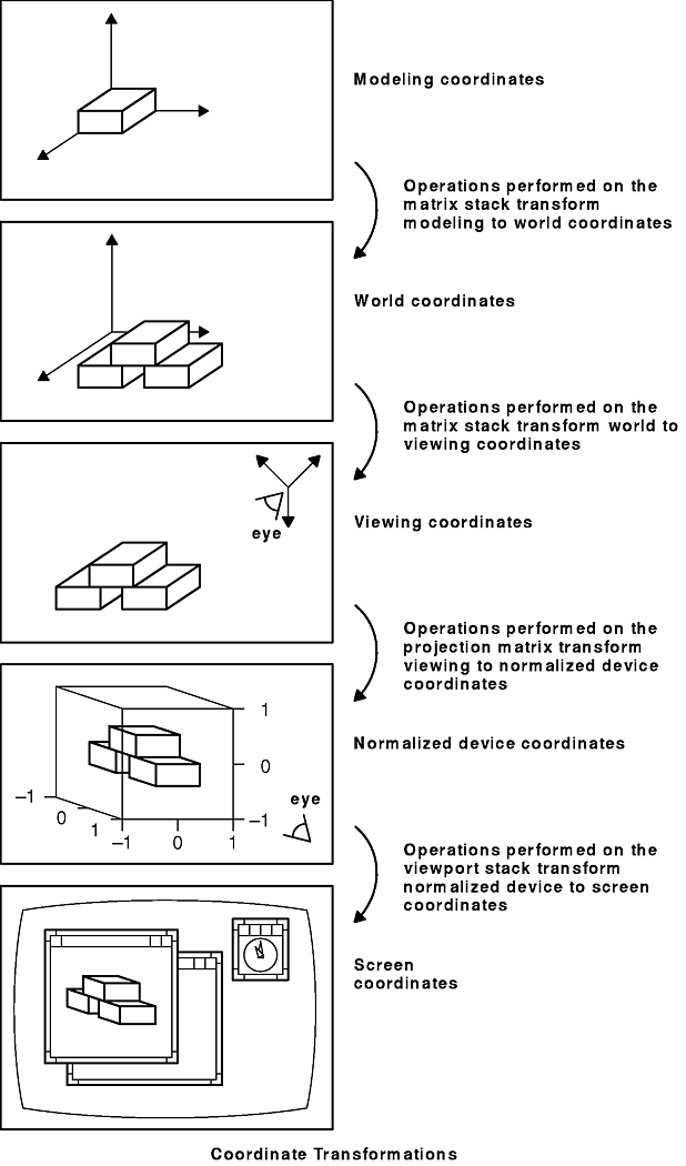
There are basically five coordinate systems of interest. First, there is a 3-D system defined in right-handed Cartesian floating-point coordinates; vertices are specified in (x,y,z) triplets. Let us refer to this as the modeling coordinate system. There are no limits to the size of sensible coordinates (other than the largest legal floating-point value).
The second system is the world coordinate system, also a 3-D floating-point coordinate system. World coordinates are used conceptually for locating the entire scene. For example, the drawing of a bolt may be defined at the origin of the modeling coordinate system (because this is the easiest way to define a bolt), but that bolt may be drawn repetitively in many different places in world coordinates.
The third is called the eye, or viewer, coordinate system. The position of all things is measured with respect to the location of the viewer's eye. GL uses the same set of subroutines to manipulate the placement of shapes in these first three coordinate systems. These subroutines become the modeling, viewing, and projection transformations, depending on the order in which they are called and the mode the system is in.
The fourth is called the normalized coordinate system. This system is also 3-D with floating-point values, but its range is limited to -1.0 ≤ x,y,z ≤ 1.0. The 3-D cube defined by these limits is convenient for clipping. After transformation to the normalized system, the clipping hardware eliminates all geometry with coordinates outside the range of -1.0 to 1.0.
The x and y coordinates of this 3-D cube are scaled directly into the fifth coordinate system, usually called the screen coordinate system. If you draw into an arbitrarily placed window on the screen, the pixel at the lower-left corner of the window has screen coordinates (0,0). Because screen coordinates represent pixel values, they are always expressed in integers, so the transformation from normalized coordinates to screen coordinates might involve some rounding and consequent loss of accuracy.
Screen coordinates are typically thought of as 2-D, but in fact all three dimensions of the normalized coordinates are scaled, and there is a screen z coordinate that can be used for many things, such as hidden surface removal and depth-cueing.
This section contains information on:
To map between the five coordinate systems, there are four distinct types of coordinate transformations. These are as follows:
These transformations are represented in the following figure.
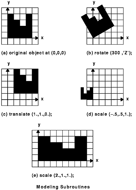
When you create a graphical object, or geometric model, the system creates it with respect to its own coordinate system. You can manipulate the entire object using the modeling transformation subroutines: rotate, rot, translate, and scale. By combining or linking together drawing subroutines, you can create more complex modeling transformations that express relationships between different parts of a complex object.
All objects drawn after these subroutines execute are transformed as specified by the individual subroutine. Therefore, controlling the order in which you specify transformation operations is extremely important.
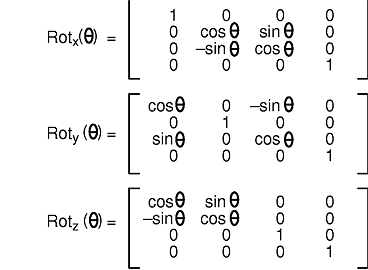
The rotate subroutine rotates graphical objects by specifying an angle and an axis of rotation. The angle is given in tenths of degrees according to the right-hand rule: if the right hand is wrapped around the axis of rotation, the fingers curl in the same direction as positive rotation, and the thumb point in the same direction as the axis of rotation. A right-handed rotation is counterclockwise. An x, y, or z character defines the axis of rotation. (The character can be uppercase or lowercase.)
Note: In the following discussion, the word object refers to the general idea of a drawn thing or shape (graphical primitive). It does not refer specifically to display lists.
All objects drawn after the rotate subroutine executes are rotated.
The rot subroutine is similar to the rotate subroutine, except that the angle is given in floating point. Both subroutines create a matrix and premultiply it into the current matrix.
The rot and rotate subroutines syntax is as follows:
void rotate(Angle angle, Char8 axis)
void rot(Float32 angle, Char8 axis)
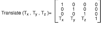
The translate subroutine moves the object origin to the point specified in the current object coordinate system. All objects drawn after the translate subroutine executes are translated. The translate subroutine creates a matrix and premultiplies it into the current matrix.
void translate(Coord x, Coord y, Coord z)
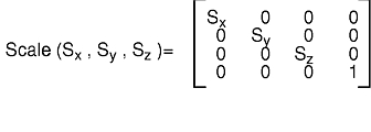
The scale subroutine shrinks, expands, and mirrors objects. Its three parameters (x, y, z) specify scaling in each of the three coordinate directions. Values with magnitudes greater than 1 expand the object; values with magnitudes less than 1 shrink it. Negative values cause mirroring.
All objects that are drawn after the scale subroutine executes are scaled. The scale subroutine creates a matrix and premultiplies it into the current matrix.
void scale(Float32 x, Float32 y, Float32 z)
The modeling subroutines are illustrated in the following figure.
The modeling subroutines are not commutative: if you reverse the order of operations, you can get different results. The following figure shows (a) a rotation of 60 degrees about the origin followed by a translation of 4 degrees in the X direction. Part (b) shows the same operation performed in the reverse order. Rotations are about the origin of the coordinate system.
The viewing transformations allow you to specify the position of the eye in the world coordinate system, and to specify the direction toward which it is looking. The polarview and lookat subroutines provide convenient ways to do this.
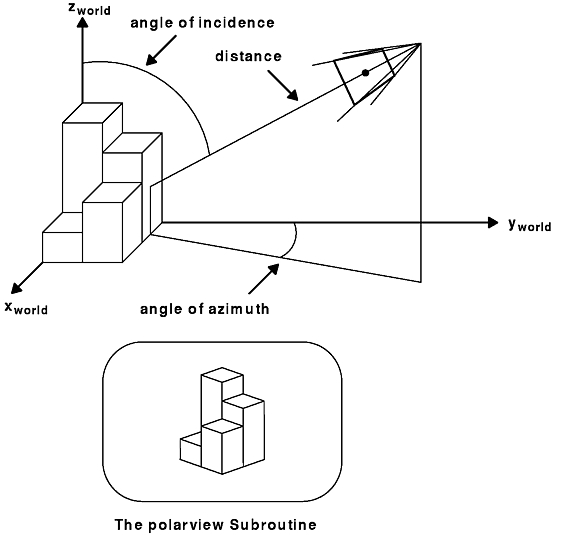
The polarview subroutine assumes that the object you are viewing is near the origin. The eye's position is specified by a radius (distance from the origin) and by angles measuring the azimuth and elevation. The specification is similar to polar coordinates, hence, the name. There is still one degree of freedom because these values tell only where the eye is relative to the object. A twist parameter tells which direction is up.
The angle of incidence equals the angle between the Z-axis in world coordinates and the location of the origin of viewing coordinates. The angle of azimuth equals the angle between the X-axis in world coordinates and the x,y coordinates of the origin of the viewing coordinates.
To understand incidence and azimuth, imagine that you are standing at the origin in world coordinates. You are facing north, along the Y-axis, with the X-axis on your right. The Z-axis points straight up, towards the zenith. There is a very large eye in the sky, looking down at you. It is located at the origin of the viewing coordinate system. This eye is the system, and whatever that eye sees appears on the screen.
Where is the eye? The azimuth is the compass point at which it is located: 0 degrees if straight north, 90 degrees if straight east, and so on, in a clockwise fashion (in conformance with astronomical usage). The incidence is the angle down from zenith: 0 degrees means the eye is directly overhead; 90 degrees means that the eye is on the horizon.
The altitude (again following astronomical usage) is precisely equal to 90 degrees minus the incidence. This coordinate system is called horizon coordinates or topocentric coordinates. The syntax is as follows:
void polarview(Coord distance, Angle azimuth, Angle incidence,
      Angle twist)
The following figure illustrates this viewpoint concept.
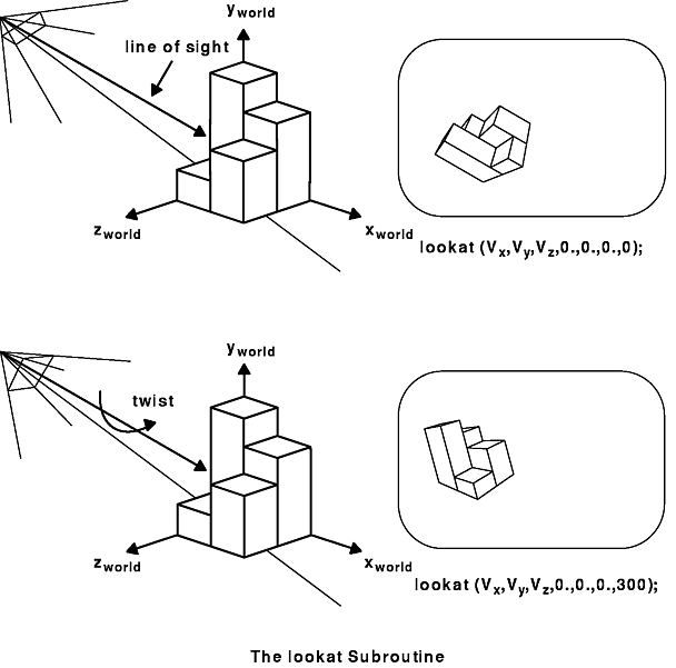
The lookat subroutine allows you to specify the eye's position in space and a point at which it is looking. Both points are given with Cartesian x, y, and z coordinates. A twist parameter specifies the angle of rotation. Once you specify the eye position, the point you are looking at could be any point along a line, and the identical transformation is specified. This viewpoint concept is illustrated in the following figure.
Both viewing subroutines work in conjunction with a projection subroutine. If you wish to view point (1, 2, 3) from point (4, 5, 6) in perspective, use the perspective and lookat subroutines in conjunction. When the orthogonal projections are used, the exact position of the eye used in the viewing subroutines does not make any difference. The only thing that matters is the viewing direction.
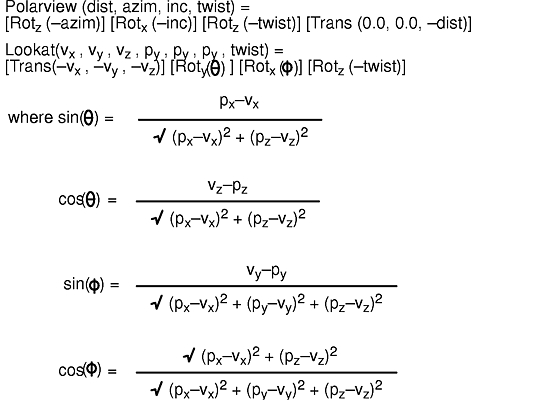
The viewing transformations work mathematically by transforming, by means of rotations and translations, the position of the eye to the origin and by adjusting the viewing direction so that it lies along the negative Z axis.
The polarview and lookat subroutines create a matrix and premultiply it into the current matrix.
Viewing items in perspective on the computer screen is like looking at them through a rectangular piece of perfectly transparent glass. Imagine drawing a line from your eye through the glass to an item. The line colors a dot on the glass the same color as the spot on the item intersected by that line. If this were done for all possible lines through the glass, if the coloring were perfect, and the eye not allowed to move, then the picture painted on the glass would be indistinguishable from the true scene.
The collection of all the lines leaving your eye and passing through the glass would form an infinite four-sided pyramid with its apex at your eye. Anything outside the pyramid would not appear on the glass, so the four planes passing through your eye and the edges of the glass would clip out invisible items. These are called the left, right, bottom, and top clipping planes.
The geometry hardware also provides two other clipping planes that eliminate anything too far from the eye or too near the eye. They are called the near and far clipping planes. Near and far clipping is always turned on, but it is possible to set the near plane very close to the eye and the far plane very far from the eye so that all the geometric items of interest are visible.
Because floating-point calculations are not exact, it is a good idea to move the near plane as far as possible from the eye, and to bring in the far plane as close as possible. This gives optimal resolution for distance-based operations such as those discussed in "Removing Hidden Surfaces" and "Performing Depth-Cueing".
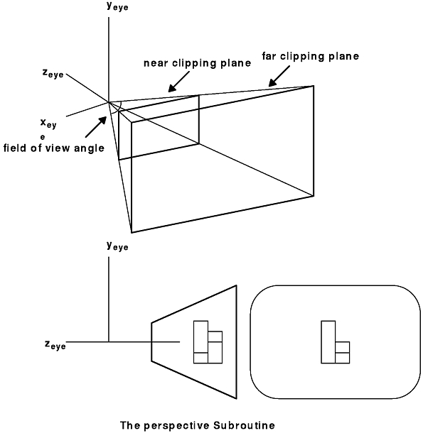
Thus, for a perspective view, the region that is visible looks like an Egyptian pyramid with the top sliced off. The technical name for this is a frustum, or rectangular viewing frustum.
The perspective subroutine maps a frustum of eye, or viewer, space so that it exactly fills the viewport. This frustum is part of a pyramid whose apex is at the origin (0.0, 0.0, 0.0), whose base is parallel to the X-Y plane, and which extends along the negative Z axis. In other words, it is the view obtained when the eye at the origin looks down the negative Z axis, and the plate of glass is perpendicular to the line of sight, as shown in the figure.
The perspective subroutine has four parameters: the field of view in the y direction, the aspect ratio, and the distances to the near and far clipping planes. Typically, the aspect ratio is chosen so that it is the same as the aspect ratio of the window on the screen, but it need not be. The distances to the near and far clipping planes are floating-point values.
Mathematically, the perspective subroutine works by mapping the 3-D volume enclosed by the viewing frustum into normalized device coordinates. Any point outside the frustum is mapped to a point outside the cube; that is, at least one of its coordinates is greater than 1.0 or less than -1.0. The clipping hardware then eliminates all the geometry outside the normalized viewing cube, and the x and y coordinates of the remaining geometry are scaled linearly to fill the window on the screen. The syntax is as follows:
void perspective(Angle fovy, Float32 aspect,
      Coord near, Coord far)
All the projection transformations work basically the same way. A viewing volume is mapped into the normalized cube, the geometry outside the cube is clipped out, and the remaining data is linearly scaled to fill the window (actually the viewport). The only differences between the projection transformations are the definitions of the viewing volumes.
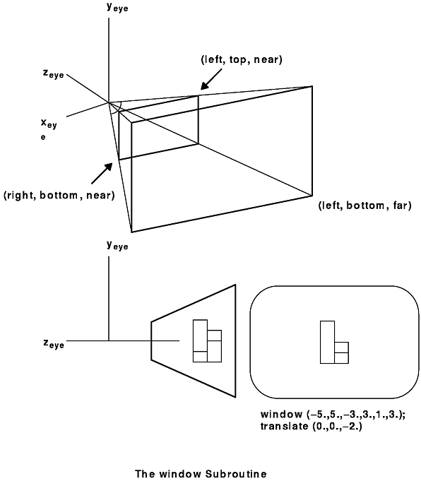
Another perspective projection transformation is the window subroutine. This subroutine is similar to the perspective subroutine, but its viewing frustum is defined in terms of distances to the left, right, bottom, top, near, and far clipping planes.
The window subroutine specifies the position and size of the rectangular viewing frustum closest to the eye (in the near clipping plane) and the location of the far clipping plane. The following figure illustrates this function, defining a viewing window in the X-Y plane looking down the negative Z axis. A perspective view of the image is projected onto the window. The syntax is as follows:
void window(Coord left, Coord right, Coord bottom,
            Coord top, Coord near, Coord far)
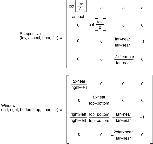
The perspective transformation subroutines create matrices and load them as the projection matrix.
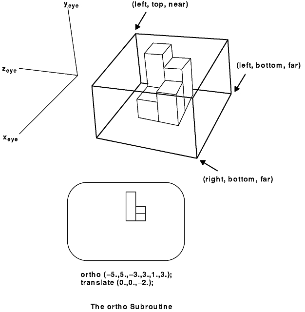
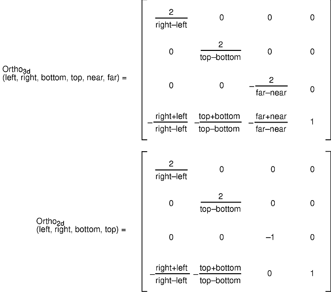
The other two projection subroutines that are part of GL are the orthogonal transformations. Their viewing volumes are rectangular boxes. They correspond to the limiting case of a perspective frustum as the eye is moved infinitely far away and the field of view decreases appropriately.
Another way to think of the ortho subroutines is that the geometry outside the box is clipped out, and the geometry inside is projected parallel to the Z axis onto a face parallel to the X-Y plane.
The ortho subroutine allows you to specify the entire box: the X, Y, and Z limits. The ortho2 subroutine, usually used for 2-D drawing, requires a specification of the X and Y limits only. The Z limits are assumed to be -1 and 1. Objects with z coordinates outside the range -1.0 ≤ z ≤ 1.0 are clipped out.
The following figure illustrates this function, defining a viewing window in the X-Y plane looking down the negative Z axis. An orthographic view of the object between the near and far planes is projected onto the window. The syntax is as follows:
void ortho(Coord left, Coord right, Coord bottom,
            Coord top, Coord near, Coord far)
The orthographic subroutines create matrices and load them as the projection matrix.