This procedure allows you to run diagnostics on your remote asynchronous node (RAN) in one of two modes:
| Front Panel Mode | Diagnostics are run from the front panel of the RAN. |
| Video Mode | Diagnostics are run from a terminal attached to the RAN. |
The diagnostics routines can test the following aspects of the RAN:
Note: Refer to "Removing or Replacing a RAN"
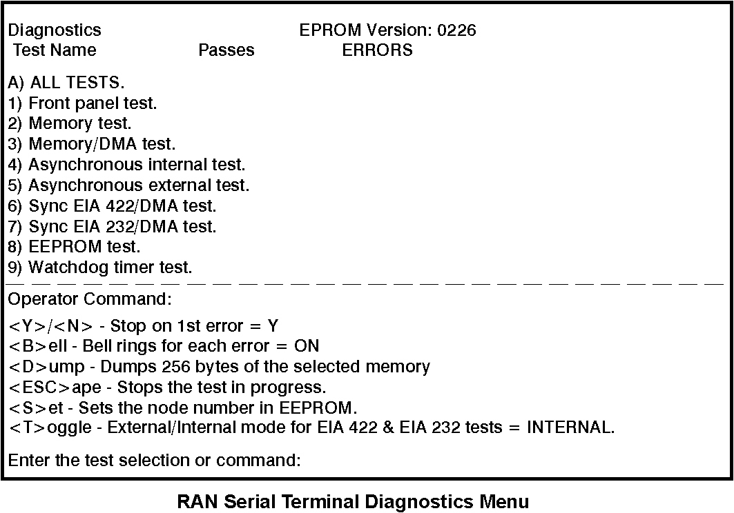
See this illustration for an example of the Diagnostics Menu displayed on the screen of the serial terminal.
Note: Some terminals (including the Wyse 60) will not transmit data if their clear to send (CTS) line is LOW. They will only transmit if CTS is HIGH or floating. When using a fully configured null modem cable, the terminal's CTS line is connected to the RAN's request to send (RTS) line, which is held LOW by the RAN until AC is displayed. This can prevent the terminal from communicating with the RAN when attempting to run diagnostics.
If you are using such a terminal, use a cable that does not have CTS connected at the terminal's end.
| 1-9 | Runs individual tests as shown on the menu. Refer to "Diagnostic Test Descriptions" for further information. |
| A | Runs all tests except test 9 (Watchdog timer test). The screen will display the number of passes run for each test. The test will halt if an error is detected if Stop on 1st is set to Y. |
| N | Runs the test continuously, keeping count of the errors detected. This must be selected prior to running the test. |
| Esc key | Cancels test execution at any time during execution. The current pass of the test will be completed and control will be returned to the terminal. |
| B | Toggles the bell option. When set to ON , the terminal beeps each time an error is encountered. |
| D | Allows you to dump 256 bytes of the RAN's memory to the screen beginning with a specified address (you will be prompted for the starting segment address). |
| S | Allows you to view or change the RAN's node number. The node number is written in three different EEPROM locations to ensure correctness of the number. |
| T | Toggles the loopback mode for the EIA 422 and EIA 232 tests (tests 6 and 7) between INTERNAL and EXTERNAL. When set to INTERNAL, the signals are looped back internally by the relays in the RAN. When set to EXTERNAL, a standard 8-wire daisy-chain cable must be installed between the RAN's IN port and its OUT/T port. |
| TEST 1: Front Panel Test | This test alternately turns on and off at one-second intervals all 10 LED indicators and all segments (plus the decimal point) of both seven-segment displays to verify proper operation of the front panel indicators. Since the indicators are write-only, the operator must visually verify success or failure of the test. |
| TEST 2: Memory Test | Each pass of this test performs a pattern test and an address tag test of DRAM. The byte pattern is incremented for each pass and is displayed on LEDs 0-7. The pattern is written to 32KB, beginning at 08000H. The pattern is written again to 32KB beginning at 10000H. The two 32KB blocks are compared to determine the pass or fail status of the test. |
| The address tag test writes 32KB beginning at address 08000H. Address 08000H will be written with 0H, address 08001h will be written with 1h, etc. This same tag pattern will be written beginning at address 10000H. The two 32KB blocks are compared to determine pass or fail status. | |
| TEST 3: Memory/DMA Test | The DMA tests DMA transfers from one memory location to another. This test may be run without being connected to the RAN. The byte pattern is incremented for each pass and is displayed on LEDs 0-7. The pattern is written to 32KB beginning at 08000H. DMA0 is used to move the 32 KB from 08000H to 10000H. When the move is complete, DMA0 interrupts the CPU and the two 32KB blocks are compared to determine pass or fail status. If the DMA transfer is not completed within 2 seconds, a time-out error causes the test to fail. |
| TEST 4: Asynchronous Internal Test | This test checks the asynchronous ports hardware. The test puts the port in local loopback mode. The four output signals (DTR, RTS, OUT1, and OUT2) are looped back within the UART chip to the four input signal lines (CTS, DSR, DCD, and RI). The following steps are completed:
This test functions differently depending on whether it is run in video mode or front panel mode.
|
| TEST 5: Asynchronous External Test | This test is used to check the asynchronous ports and their associated driver and receiver circuits. Loopback plugs are required. See "RAN Diagnostics Loopback Plug" for more information. These plugs enable one asynchronous port to transmit and receive data. The following steps are completed:
This test functions differently depending on whether it is run in video mode or front panel mode.
For repeated testing of a single port, front panel mode is recommended. |
| TEST 6: Sync EIA 422/DMA Test | This test uses DMA0, DMA1, and the SCC 8530 sync port to transmit, receive, and verify data using the EIA-422 circuitry. The byte pattern is incremented for each pass and is displayed on LEDs 0-7. The pattern is written to a block of memory beginning at address 08000H.
DMA0 (Rx) and the sync port are used to move the block of data from 08000H to 10000H. The test checks three modes of synchronous data transmission: 8-wire, 1.2 Mbps (32K-byte blocks); 4-wire NRZI, 230 Kbps (8K-byte blocks); and 4-wire FMO, 460 Kbps (16-byte blocks). When the move is complete, the sync port generates an interrupt and the two blocks are compared to determine pass or fail status. If the DMA transfer using the sync port is not completed within 2 seconds, a time-out error causes the test to fail.
|
| TEST 7: Sync EIA 232/DMA Test | This test uses DMA0, DMA1, and the SCC 8530 sync port to transmit, receive, and verify data using the EIA-232 circuitry. The byte pattern is incremented for each pass and is displayed on LEDs 0-7. The pattern is written to 512 bytes beginning at address 08000H. DMA1 (Tx), DMA0 (Rx), and the sync port are used to move the 512 bytes of data from 08000H to 10000H at an SDLC rate of 19200 baud. When the move is complete, the sync port generates an interrupt, and the two 512-byte blocks are compared to determine pass or fail status.
If the DMA transfer using the sync port is not completed within 2 seconds, a time-out error causes the test to fail. An audible relay click will be heard upon entering and exiting this test. In video mode, this test can be run with either internal or external loopback by pressing T on the terminal. The external mode requires a standard 8-wire daisy-chain cable to be installed between the RAN's IN port and OUT/T port. |
| TEST 8: EEPROM Test | This test generates a checksum of the EPROM contents and compares it with the checksum stored in the EEPROM. If the checksums match, the test passes. This does not write to the EEPROM (EEPROM write operations only occur when a new node number is set). |
| TEST 9: Watchdog Timer Test | This test checks out the watchdog timer. This is a hardware feature that is used to ensure system reliability. When the watchdog timer is loaded and enabled, the timer begins counting down. It is up to the system to keep reloading the timer to prevent it from expiring. If the timer expires, the hardware forces the CPU into a reset state and the POST sequence is started (exactly as if the concentrator is turned off and then on again). Normal test execution allows the timer to expire and force POST execution. The test fails after 1 second if the timer has not expired. |