There are three basic wiring modes for connecting remote asynchronous nodes (RAN) to an adapter or to each other:
Additionally, there are four types of modular plugs that can be used to connect your asynchronous device to the RAN's RJ-45 10-pin jack:
This article discusses the following cables and jacks including their pin-outs and uses.
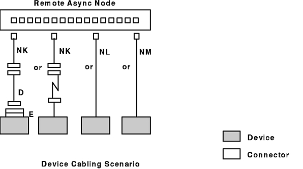
The following figure illustrates three general methods for attaching remote asynchronous nodes (RANs) to the 128-port asynchronous adapter.
Note: *Contact your sales representative for information on the 4-wire direct and synchronous modem cables.
In order to make the necessary connections to the 128-port asynchronous adapter, your setup person needs to know the type of connection and which cables to use. The following cable planning chart shows what cables are used.
| Cable Planning | |
|---|---|
| Cable Letter | Name/Description |
| NC | 8-Wire Daisy-Chain cable (9 in.) |
| NB | 8-Wire Daisy-Chain cable (15 ft) |
| ND | 4-Wire Daisy-Chain cable |
| NE and NF | 8-Wire EIA 232 Synchronous Modem cables |
| NG and NH | 8-Wire EIA 422 Synchronous Modem cables |
| NL | RAN-to-Device EIA 232 cable |
| NM | RAN-to-Modem EIA 232 cable |
| NK2 | RJ-45 to DB-25 Converter cable (4 cables in a kit) |
| D2 | EIA 232 Asynchronous cable |
| E2 | EIA 232 Printer/Terminal Interposer |
Notes:
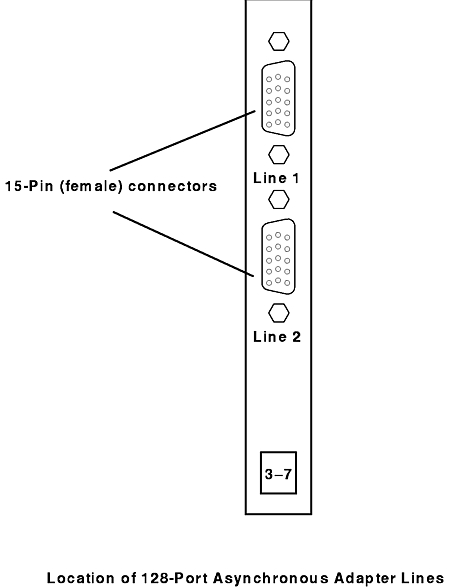
The following figure illustrates the location of the EIA 422 channels or lines of the 128-port asynchronous adapter.
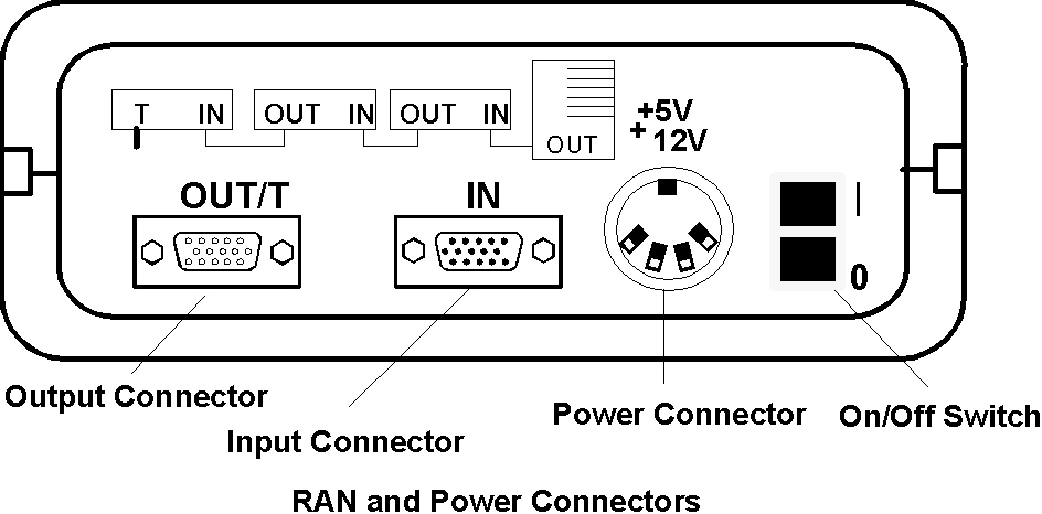
The following figure illustrates the RAN's connectors, power connectors, and its On/Off switch.
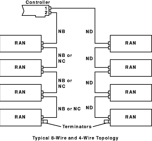
The following figure shows a typical configuration in which eight RANs are attached to the 128-port asynchronous adapter using both 4-wire and 8-wire cabling.
Note: 8-wire cabling cannot be used in combination with 4-wire cabling on the same adapter line.
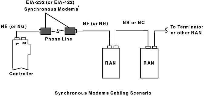
The following figure illustrates the use of EIA 232 or EIA 422 synchronous modems in typical 128-port asynchronous adapter configurations. Note that each configuration requires a unique set of customer-supplied cables for modem attachment.
Note: * Cables NE, NG, NF, and NH are not available from IBM.
Any combination of 8-wire cabling and synchronous modems can be used to attach remote asynchronous nodes. However, 4-wire cabling cannot be used in combination with synchronous modems on the same adapter line.
Note: Only one pair of synchronous modems can be used per adapter line.
A choice of cables can be attached to any of the 16 RAN ports. These ports are labeled 0 through 15 and accept 4-, 6-, 8-, and 10-pin RJ type connectors. Refer to the following figure for an example of device cabling. The device can be a display, a printer, or a plotter.
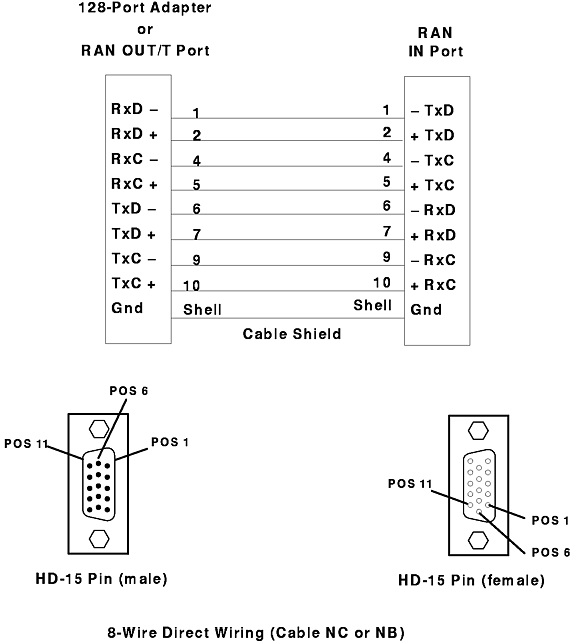
8-wire direct is the standard method for connecting RANs to the 128-port adapter. It provides transmit and receive data signals plus discrete clock signals for transmit and receive data. This permits synchronous data rates of up to 2.458 Mbps, which results in the maximum data throughput under moderate to heavy loads. See the following figure for an illustration of the 8-wire direct daisy-chain cable.
The maximum length of a daisy chain is dependent on the synchronous data rate used for the 128-port line to which it is connected. The following table lists the maximum "cumulative" daisy-chain cable lengths for various line speeds or baud rates.
| Baud Rate | Maximum Cable Length (24 AWG Twisted Pair, 12 pF/ft) |
| up to 460K | 2000 ft |
| up to 1.2M | 1000 ft |
| up to 2.4M | 300 ft |
Note: The information in this table represents the maximum "recommended" supported configurations and are intended for general guidelines only. Configurations above these recommendations can be used, but be aware that, depending on your particular operating environment, loss of data integrity and possible hardware failures may occur.
For example, to run a synchronous line at 1.2 Mbps, the total length of all daisy-chain cables for that synchronous line cannot exceed 1000 ft. Therefore, a single RAN could be placed 1000 ft from the host adapter, or four RANs could be spaced at 250-ft intervals and still operate at 1.2 Mbps.
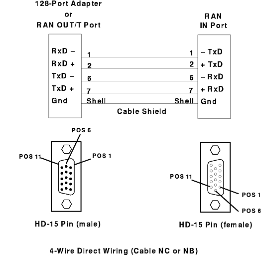
4-wire direct wiring can be used to connect RANs where longer synchronous cable runs are necessary. While not as fast as 8-wire connections (the maximum data transfer rate is 460 Kbps), this wiring method is more economical and is sufficient in all but the most demanding high-performance applications (terminal users should see no degradation in performance). In the 4-wire direct-wiring mode, the clock signals are encoded with the receive and transmit data signals (non-return-to-zero inverted encoding at 230 Kbps and FM0 encoding at 460 Kbps), so only two twisted pairs are required.
The cable has four conductors, two twisted-pair, and is shielded on the outside. If built to a length of 300 m (1000 ft) or less, conductors should be 28 AWG (stranded wire) with a capacitance rating of 52 pF/m (16 pF/ft) or less (Belden type 9804 or equivalent). For lengths greater than 300 m (1000 ft), conductors should be 24 AWG (stranded wire) with a capacitance rating of 52 pF/m (16 pF/ft) or less (Belden type 9829 or equivalent).
See the following figure for an illustration of the 4-wire direct daisy-chain cable.
Note: The 4-wire direct daisy-chain cable is a customer-supplied cable.
The 128-port asynchronous adapter supports two adapter line-baud rates in 4-wire direct-attach mode. The following table shows the maximum allowable adapter line length for each supported baud rate. The adapter line length is the actual cable length from the adapter to the last remote asynchronous node in the adapter line.
| Adapter Line Baud Rate | Total Adapter Cable Length | |
| bps | m | ft |
| 230000 | 400 | 1350 |
| 460000 | 300 | 1000 |
Note: This table assumes no intermediate connectors between remote asynchronous nodes. Each additional connection will decrease the maximum allowable adapter line length by approximately two percent due to increased line capacitance.
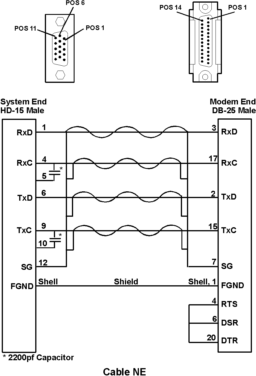
8-wire synchronous modem wiring allows RANs to be installed in remote locations and connected to the adapter using EIA 232 or EIA 422 synchronous modems. The 128-port asynchronous adapter and the RAN are designed so that the synchronous ports can support either EIA 422 or EIA 232 line levels.
The following figure, Cable NE, shows a 128-Port asynchronous controller EIA 232 modem cable and system.
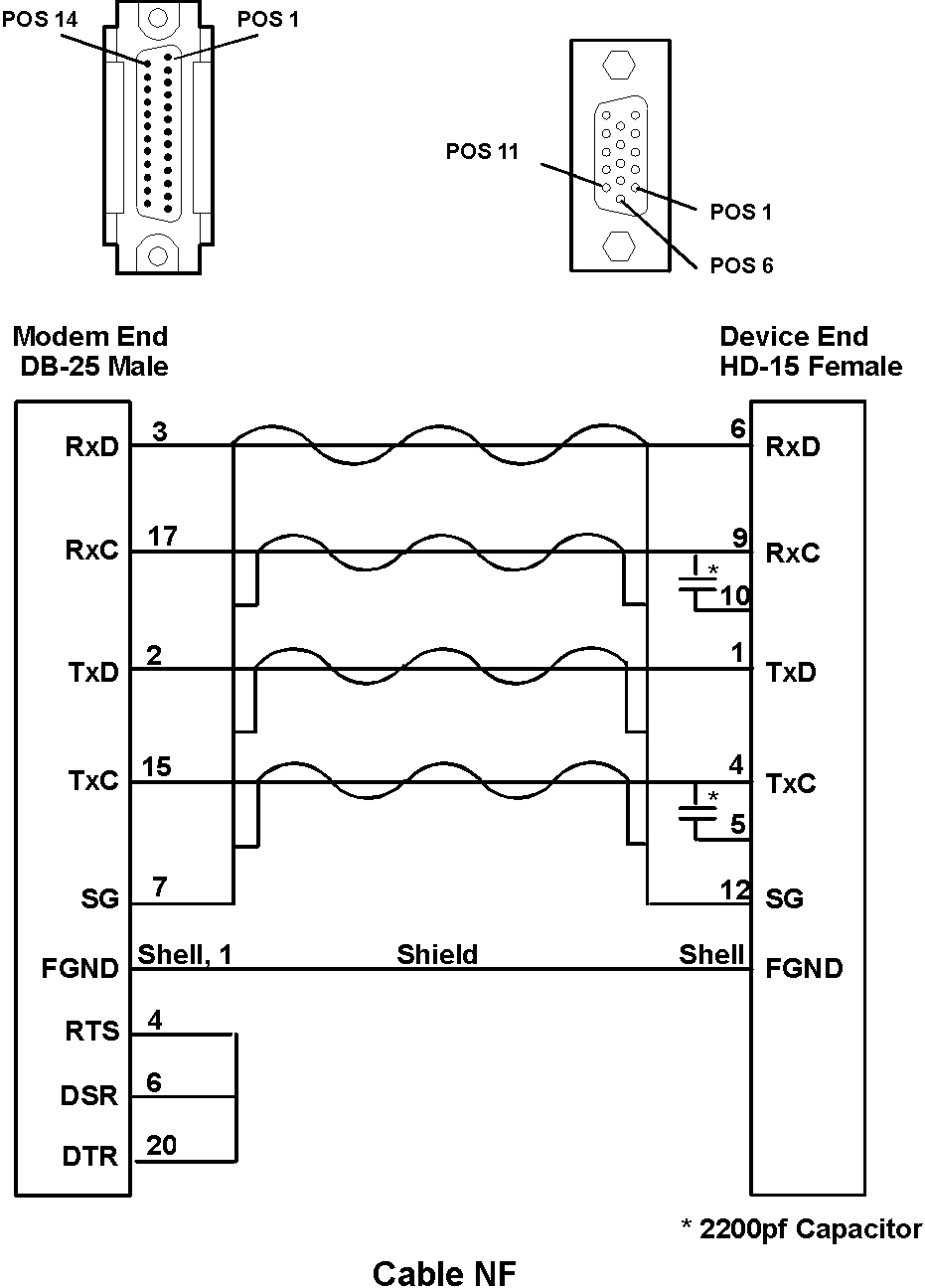
The following figure, Cable NF, shows a 128-Port asynchronous controller EIA 232 modem cable and device.
The cable has eight twisted-pair conductors and is shielded on the outside. Cable length can be from 1.8 m (6 ft) to 3.7 m (12 ft). Conductors should be 24 AWG (stranded wire) with a capacitance rating of 41 pF/m (12.5 pF/ft) or less.
The 128-port asynchronous controller supports multiple controller line baud rates in EIA 232 synchronous-modem-attach mode. However, to ensure data integrity, controller line baud rates of 57.6 Kbps or less are recommended.
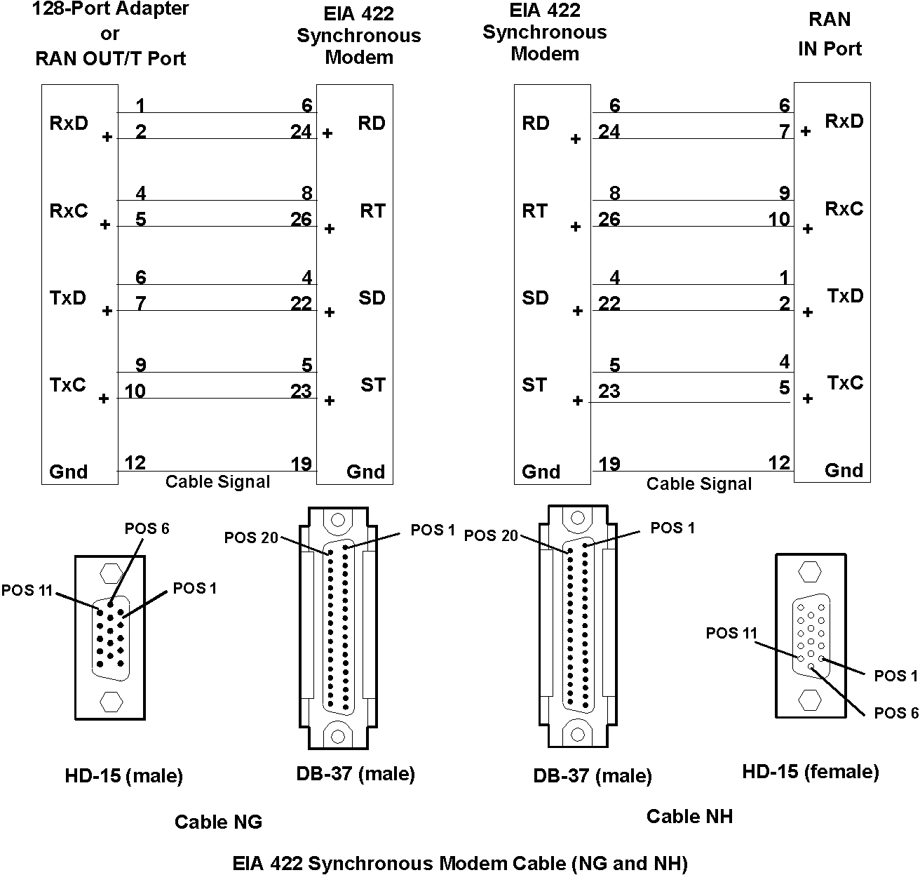
The cable has eight conductors, four twisted-pair, and is shielded on the outside. If built to a length of 300 m (1000 ft) or less, conductors should be 28 AWG (stranded wire) with a capacitance rating of 52 pF/m (16 pF/ft) or less (Belden type 9806 or equivalent). For lengths greater than 300 m (1000 ft), conductors should be 24 AWG (stranded wire) with a capacitance rating of 52 pF/m (16 pF/ft) or less (Belden type 9831 or equivalent).
The following figure shows the 128-port asynchronous adapter supporting multiple adapter line-baud rates in EIA 422 synchronous modem-attach mode. See the Adapter Line Baud Rate table.
There are four types of modular plugs that can be used with the RAN RJ-45 10-pin jack:
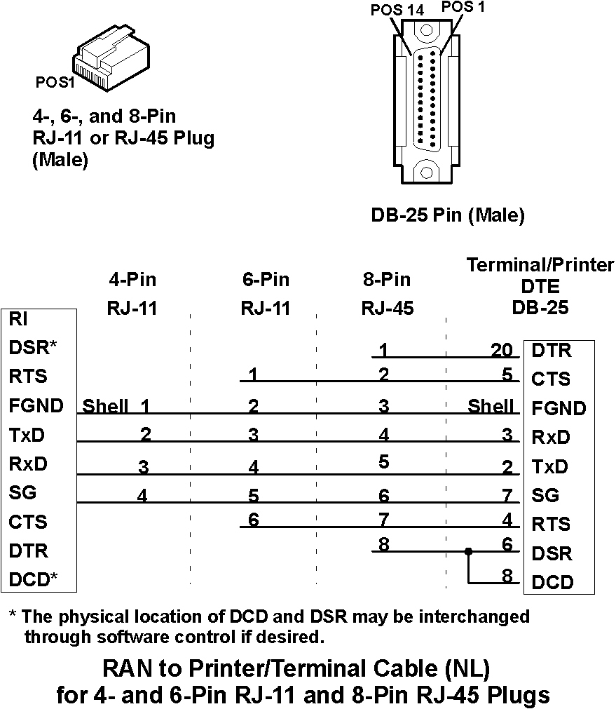
The following figure, Cable NL, shows a customer-supplied cable for connecting remote asynchronous node 16-Port EIA 232 to a printer or terminal device.
Cable length can be up to 61 m (200 ft). For 115Kbps the maximum cable length is 80 ft. For 230Kbps the maximum cable length is 40 ft. Use overall foil/braid shielded multiconductor cable with a capacitance rating of 41 pF/m (12.5 pF/ft) or less. Conductors should be 28 AWG (stranded wire). For lengths less than 61 m (200 ft), higher capacitance cable can be used, as long as the total capacitance (including intermediate connectors and cables) does not exceed 2500 pF.
The following diagram illustrates cable NL using a 10-pin RJ-45 plug.
Attention: The receivers and drivers used in most asynchronous communications devices are sensitive to electrostatic discharge (ESD). To reduce the possibility of exposure to ESD, observe the following cabling practices when building or using device cables for attachment to the RAN 16-Port EIA 232:
- Do not build a cable that has exposed conductors, leads, or pins that could be touched by someone not protected against ESD. Avoid the use of punchdown blocks and patch panels which have exposed terminator/pins. If you use intermediate connectors or cables, be sure to discharge them to ground before plugging them into equipment.
- Do not run any cables outdoors without having proper transient voltage suppression devices installed.
- Do not route cables near or around items such as power transformers, high-power switching devices, and refrigeration units.
- Use shielded cables. All wires should be terminated, not floating. The shield should be connected to shield ground at the remote asynchronous node.
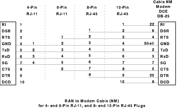
Cable NM is used to connect modems to the RAN's RJ-45 connectors. See the following diagram for an illustration of the cable NM and EIA 232 using 4- and 6-pin RJ-11 and 8- and 10-pin RJ-45 plugs.
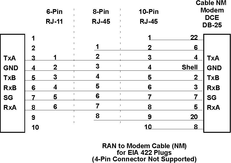
The following diagram shows cable NM and EIA 422 using 6-pin RJ-11 and 8- and 10-pin RJ-45 plugs.
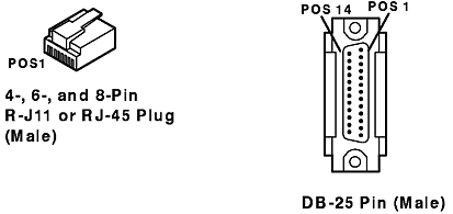
The following diagram illustrates the plugs used with cables NL and NM.
Notes:
Cable length can be up to 61 m (200 ft). Use overall foil/braid shielded multiconductor cable with a capacitance rating of 41 pF/m (12.5 pF/ft) or less. Conductors should be 28 AWG (stranded wire). For lengths less than 61 m (200 ft), higher capacitance cable can be used, as long as the total capacitance (including intermediate connectors and cables) does not exceed 2500 pF.
The 8- and 10-pin RJ-45 connections are suitable for both terminal and printer attachment. The 4- and 6-pin RJ-11 connections are not recommended for printer attachment.
The 10-pin RJ-45 plug carries all eight of the EIA 232 signals supported by RANs, plus the two ground lines, Signal Ground (SG) and Chassis Ground (GND). The 10-pin configuration includes the modem control lines Ring Indicator (RI) and Data Carrier Detect (DCD).
The 8-pin RJ-45 plug supports all of the EIA 232 signals except the modem control lines RI and DCD. It is ideal for use with terminals and printers that require full hardware handshaking, both Data Set Ready (DSR) and Clear To Send (CTS) must be satisfied for data transmission to occur.
Note: The physical location of DCD and DSR may be swapped. The operating system permits software "rewiring" of the RJ-45 connectors so that DCD is available in 8-pin configurations. When connecting to Data Terminal Equipment (DTE) devices (such as terminals and printers), you can either use the standard configuration shown above, or the ALTPIN configuration (see "RJ-45 Connection to Modem Considerations").
6-pin RJ-11 plugs can be used in hardware handshaking situations that require only RTS and CTS to be available. This cable is not recommended for printer attachment.
The 4-pin RJ-11 plug can be used in situations requiring software flow control (XON/XOFF) but no hardware handshaking. No hardware handshake lines are available with this configuration. This is useful for the popular "three-wire" connection (TxD, RxD, and SG) used for terminals that support XON/XOFF handshaking. The 4-pin plug is not supported for printers that must have CTS connected to work properly.
When using the 4-pin plug with terminals, DCD sensing must be disabled in the software. This can be done with SMIT, or with the command:
chdev -l ttyXX -aforcedcd=enable
Modems are generally equipped with DB-25 connectors, and the NE cable is suitable for this use. Since the modem control lines RI and DCD are on pins 1 and 10, respectively, of the RAN RJ-45 jack, the 10-pin RJ-45 plug is ideal for modems.
Due to the wide availability of RJ-45 8-pin cable, the AIX operating system software incorporates an optional feature called ALTPIN, which swaps the logical functions of DSR with DCD. When ALTPIN is enabled, DCD becomes available on pin 1 of an 8-pin RJ-45 connector (equivalent to pin 2 of a 10-pin connector).
The operating system does not require DSR in modem-control applications, and since almost all of today's modems have auto-answering capability, the RI signal is generally unnecessary.
Cable length can be up to 61 m (200 ft). Use overall foil/braid shielded multiconductor cable with a capacitance rating of 41 pF/m (12.5 pF/ft) or less. Conductors should be 28 AWG (stranded wire). For lengths less than 61 m (200 ft), higher capacitance cable can be used, as long as the total capacitance (including intermediate connectors and cables) does not exceed 2500 pF.
The forcedcd option must be set to enable. The 422 RAN defaults to forcedcd=enable. The 4-pin RJ-11 connection is not supported. Hardware flow control is not supported for EIA 422 connections. XON/XOFF flow control should be used.
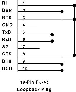
The loopback plug is used during the RAN diagnostic asynchronous external test to enable an asynchronous port to transmit and receive data. This plug is not supported for EIA 422.
The loopback plug consists of a single 10-pin RJ-45 plug wired as follows:
Refer to the following figure for an illustration of the wiring of the RJ-45 loopback plug.