This section contains installation information for hardware and software. When you have completed the installation procedures, refer to "Configuring a 7318 Model P10".
Refer to Chapter 2, "Serial Communications Network Server (7318) Installation," in the 7318 Model S20 Guide and Reference for information specific to the 7318 Model S20.
Observe the following safety instructions any time you are connecting or disconnecting devices attached to the workstation.
DANGER: An electrical outlet that is not correctly wired could place hazardous voltage on metal parts of the system or the devices that attach to the system. It is the responsibility of the customer to ensure that the outlet is correctly wired and grounded to prevent an electrical shock.Before installing or removing signal cables, ensure that the power cables for the system unit and all attached devices are unplugged.
When adding or removing any additional devices to or from the system, ensure that the power cables for those devices are unplugged before the signal cables are connected. If possible, disconnect all power cables from the existing system before you add a device.
Use one hand, when possible, to connect or disconnect signal cables to prevent a possible shock from touching two surfaces with different electrical potentials.
During an electrical storm, do not connect cables for display stations, printers, telephones, or station protectors for communications lines.
CAUTION:This product is equipped with a three-wire power cable and plug for the user's safety. Use this power cable in conjunction with a properly grounded electrical outlet to avoid electrical shock.
DANGER: To prevent electrical shock hazard, disconnect the power cable from the electrical outlet before relocating the system.
To install the 7318 hardware, follow these four basic steps:
The 7318 can be positioned on any surface, provided you do not block the air flow from the front and rear of the unit.
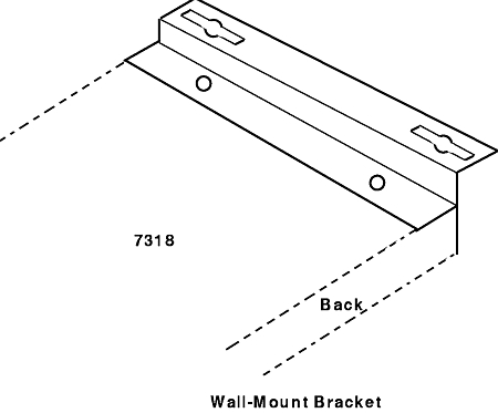
Wall mounting works well for a single 7318. When mounting multiple 7318s, install a shelf on the wall and place the 7318s on the shelf or use an EIA rack.
Use rack mounting to install one or more 7318s in a single location. Mount the 7318 in the rack, using the optional rack-mounting brackets, or place the 7318s on a standard rack shelf.
To mount the 7318 in an EIA rack:
The following information briefly describes the choices for attaching to a network. You can choose between attaching the 7318 to a host adapter, a hub, or an external Ethernet transceiver. For more information, refer to "Ethernet Overview". The following cables are available for network attachment:
The AUI port connects the 7318 to an external transceiver (Part Number 02G7437 for Thin or Part Number 02G7431 for 10BaseT) for the Ethernet network. You can use AUI or 10BaseT but only one can be active at a time (unless in a high-availability [HA] environment). The AUI port supports a directly attached transceiver or a cable to a remote transceiver. AUI transceiver cables are specially designed for this application and normally come with the transceiver. Refer to "Ethernet Overview" for more information.
If you are in an HA environment, attach cables to both the AUI and T ports, one to each Ethernet network.
Note: Only one Ethernet network is used at a time.
See "7318 High-Availability Environment for the Model P10" for more information.
You can use standard 10BaseT unshielded twisted-pair (UTP) cable to connect to a 10BaseT hub. There are no performance advantages to using a particular Ethernet port on the 7318.
When attaching to a 10BaseT hub, connect the cable from the hub to the T port on the 7318. Use the T port as the second Ethernet connection in an HA environment.
As with the T port, you can use standard 10BaseT unshielded twisted-pair (UTP) cable to connect to a 10BaseT host adapter. There are no performance advantages to using a particular Ethernet port on the 7318.
Unlike the T port, when attaching directly to a 10BaseT host adapter, connect the cable from the host adapter to the T-X port on the 7318. The following procedure explains this simple installation process. In this instance, other network hosts share the 7318 only through the attached host.
To install a 7318 directly to a host:
Note: If you need a longer cable than the 10 foot RJ-45 to RJ-45 cable (Feature Code 7901), be sure to use a cable designed for 10BaseT. Refer to "Twisted Pair Cable" for more information on the appropriate type of cable to use.
If you are planning to connect more than one 7318 to the network, you can either connect the 7318s individually or use daisy-chain connectors. Using the daisy-chaining feature reduces the number of hub or host adapter connectors required for the additional 7318s.
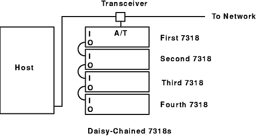
Using the 7318 I (In) and O (Out) ports and daisy-chain cable, you can attach up to four 7318s to the same Ethernet connection. This reduces the need for separate transceivers and additional 10BaseT hub ports. Daisy-chained 7318s each maintain their own Ethernet and IP addresses, load, and operate independently. The P10s and S20s may be mixed in a single daisy chain.
Use the daisy-chain cable (Feature Code 7909) to connect one 7318 to another. You must remove power to all 7318s in the daisy-chain group before installing a daisy-chain cable. If you plug in a daisy-chain cable to an operating unit, the Ethernet interface will not operate properly. You must power cycle the unit, because the 7318s recognize their daisy-chain configuration only when they power up.
The 7318 that is attached to the Ethernet is called the "first" in the chain. Only the first 7318 is connected to the Ethernet; the rest are connected through the daisy-chain connectors.
The additional 7318s are attached in order; that is, the second is attached to the first, the third to the second, and the fourth to the third. The last 7318 in the line is connected to only one other. Use the O (Out) connector of the higher 7318 to connect to the I (In) connector of the lower 7318.
The Daisy-Chained 7318s figure illustrates the cabling relationship among four daisy-chained 7318s as well as their relationship to the host.
While the daisy-chain feature is easy to use, you must observe a few rules when chaining 7318s:
The 7318 does not provide a power on/off switch. You must use the AC plug to power on and power off the 7318.
Plug in the 7318 to ensure that the server is functional. The lights on the front will turn on or stay off in different configurations depending on the state of the 7318, the download, and the network.
The operation of these lights is as follows:
Note: Ethernet transceivers must support SQE heartbeat for the AUI light to function properly. If your transceiver does not support SQE heartbeat, the AUI light will not light.
Note: Daisy-chained 7318s only display the AUI port light, even if the first 7318 is connected using the 10BaseT (T or T-X) port.
You can now attach the cables for terminals, printers, and modems to your 7318. "Wiring Serial Devices" describes serial devices such as terminals, modems, and serial printers. "Connector Pinouts" describes the pinouts for all cables. The following cables are available for attaching devices:
Each cable measures 10 ft in length.
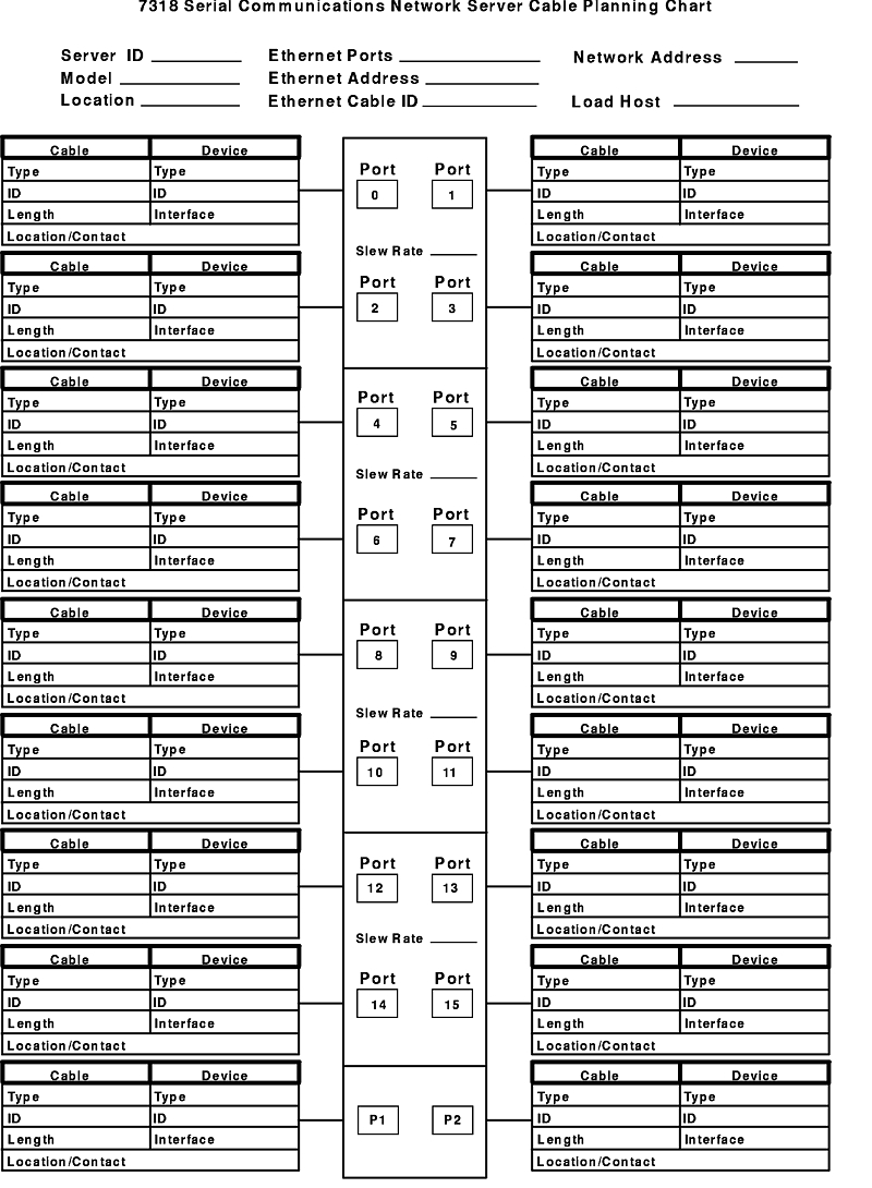
Use the 7318 planning chart to assist you in planning your cable configuration. There is a blank chart for your use following the example.
To install the protocol software and configure the system and devices, use the System Management Interface Tool (SMIT). The following information describes the installation and system-configuration process for Version 3.2.
Notes:
- If Netware V3.11x will be concurrently operating with the Async Terminal Server-Accelerator/6000 licensed programming product, it is strongly recommended that the most current program temporary fix (PTF) for NetWare V3.11 be installed. If this is not done, client users may likely experience degradation in network performance.
- Software prerequisites might be installed automatically through the following procedure.
The following steps will help you install the software:
The following describes the contents of the package to install.
| p10 | SMIT menus, cnsview, p10 bootfile, p10 default configuration file. |
cns.p10.obj
Install for Model P10 support
cns.s20.obj
Install for Model S20 support
cns.s20export.obj
The following information describes the installation and system-configuration process for AIX Version 4.1.
devices.7318.com
Common support, not explicitly installed
devices.7318.p10
Install for Model P10 support
The following information describes the installation and system-configuration process for AIX Version 4.2 (and later).
bos.cns
Install for 7318 Model P10 and S20.
bos.cns.s20des
Install for 7318 Model S20 with DES data encryption.
The 7318 Model P10 uses the SPX/IPX protocols for communication with the system. SPX/IPX use a different addressing method than IP addressing. Similar to IP addressing, each node on a network has a unique address. However, with IPX, each network segment has its unique identifier also.The system is given a node address in the NPSConfig file located in the /etc/netware directory. The internal_network field in this file specifies the node address for the system. The complete address of the system will be the internal_network number followed by a colon and the number 000000000001. For example:
00000005:000000000001
The NPSConfig file is also used to define the network segment identifier to the system. If there are multiple network adapters in the system, there will be a network segment identifier for each adapter card. This network segment identifier is defined by the lan_x_network field in the NPSConfig file, where x is the number associated with the adapter card stanza in the file.
Typically, the default network segment identifier is 00000002, and the NPSConfig file entry for lan_x_network is:
lan_1_network=00000002
The 7318 automatically defines its SPX/IPX address to be the network segment identifier plus its Ethernet MAC address. The MAC address is found on the back panel of the 7318. For example:
00000002:00406e000321
Medium access control (MAC) addresses are unique to each 7318, so each 7318 on a network has a unique address. The 7318 detects the network segment identifier during the boot process using Service Advertising Protocol (SAP) broadcast packets that are sent by SPX/IPX nodes on a network.
During the SMIT configuration process for adding a 7318, you must complete two fields that define to the software the 7318's SPX/IPX address. Therefore, you need to know the network segment identifier for the segment the 7318 is attached to and its MAC address.
For a 7318 attached to a network segment shared with the system, the network segment identifier can be found in the NPSConfig file (lan_x_network). For a 7318 attached to a remote Ethernet, the information must be obtained from the router or another SPX/IPX node on that network.
In the remote Ethernet configuration, the ComNetServer Network Address field in SMIT must be set to the network segment identifier and not the lan_x_network number in the system's NPSConfig file.
After installing the software, add the 7318 devices to your AIX system. Repeat these steps for each 7318 you add to the network. For example, if you are adding two 7318s, you must run these steps twice, indicating a different 7318 (by Ethernet address) each time.
The following steps define an SPX/IPX network address, an Ethernet hardware address, an interface type, and a boot file name. Depending on your choice, network ttys and virtual ttys can be generated as well.
Notes:
- Generating ttys and virtual ttys from this dialog is much faster than generating them one at a time later.
- You must select ttys and virtual ttys for a port to use transparent print. Refer to "Configuring a Transparent Printer for a Model P10".
The following information details steps to create a tty device for a specific session and port on a 7318.
If you generated virtual devices on any host for your Model P10 ports and you plan to configure a single port for multiple hosts, refer to "Configuring Ports for Dedicated or Multiple Hosts" for important configuration information. The following information explains how to enable a tty on the host. You must enable the tty to start a getty process, which is a prerequisite to obtaining a login screen.
You must have root user authority.
To enable a tty effective on the next system reboot, use the following steps:
Repeat the previous steps for each terminal you want to enable. By default, all ports are enabled at 9600 baud, 8-bit characters, 1 stop bit, and no parity. Using these settings, you can hook up most terminals to start using your 7318. To add terminals, printers, or modems that do not use these default settings, refer to "Installing a Terminal with Defaults", "Installing and Configuring Printers", and "Modems".
penable ttyXwhere the X parameter specifies the tty number to enable. Use the /usr/lpp/cns/samples/build_ttys (on AIX Version 3.2.5) or the /usr/samples/7318/build_ttys (on AIX Version 4) sample shell script to enable a large number of ttys.
Note: The penable command does not change the ODM database. Perform steps 2 through 8 to ensure that your ttys are enabled with each system startup.
Use the following information if you are removing a 7318 Model P10 from a host.
Use SMIT to remove a 7318 from your system. Removing the 7318 also removes all serial and parallel port attached devices as well. Repeat the following steps for each 7318 you are removing from the host. (Since each port can have multiple sessions, it is not necessary to remove sessions from one host to configure them on another host.)
The following steps will help you remove the software for upgrades or remove the package from your system.
The following steps will help you remove the software for upgrades or remove the package from your system.
You must have root user authority.
The following steps will help you remove the software for upgrades or remove the package from your system.
You must have root user authority.
Use your favorite editor and the System Management Interface Tool (SMIT) to fill in the blanks from the /etc/netware/NPSConfig file:
| Host Name | Host 1 | Host 2 |
|---|---|---|
| From the Host: | Host 1 | Host 2 |
|---|---|---|
| Check for spx = active. If active is not specified, change to active and consult your network administrator to verify the other SPX/IPX network administrator. | ||
| Find the host's internal_network= number. This must be unique for all hosts on the network. | ||
| Find Netware's Ethernet interface: | ||
| lan_x_if_name= | ||
| lan_x_ppa = | ||
| lan_x_network = | ||
| Fill in the Ethernet interface being used (concatenate the _ if_name and _ ppa fields, for example, en0 ) | ||
| Check to see that the Ethernet interface is running. (Use the smit chinet command and select the correct interface.) | ||
| (Check when complete) | ||
| rcnetw uncommented in /etc/inittab |
| From the 7318 Model P10: | ||
| Serial Number | ||
| Ethernet Address (see back of unit) | ||
| Ethernet Port(s) connected (circle all that apply) | AUI T TX Daisy-Chain | |
| Using SMIT: | ||
| Device Number (01-99) | ||
| Auto-Generated Devices | ttys only, ttys and virtuals, none | ttys only, ttys and virtuals, none |
| Interface Type | EIA 232 EIA 422 | EIA 232 EIA 422 |
| Host Enabled to Boot the 7318 (YES, NO) | ||
The example of the 7318 Terminal Server Cable Planning Chart shows connections for six terminals, one modem, one serial printer, and one parallel printer. The IDs assigned in the example are assigned by the configuration planner. A blank chart is available on the following page.