The following describes how to configure terminals and multiple sessions, printers, and modems. Configuring a Model P10 for a multihost environment as well as a high-availability environment is also explained.
Use the following procedure to install a terminal, using the default settings. Later information gives details on modifying the terminal settings and specifics about terminal types.
This completes the installation of terminals that use the default settings. The following information describes other configurations, as well as commands that report the state of the terminal settings. Two additional features of the 7318 Hibaud capability and multiple sessions, are also described.
When you installed the 7318, you specified the initial configuration of the terminals. You can change the configuration for any terminal, using the System Management Interface Tool (SMIT).
You must have root user authority.
The following steps change the configuration of a terminal:
Note: The tty baud rate must be the same as the device baud rate.
The 7318 has the ability to operate at data rates in excess of the 38.4 Kbps supported by AIX. To use a port at rates above 38.4 Kbps, you must set the Hibaud property for that port. Hibaud causes certain data rates set and reported by the smit command to be reinterpreted as higher rates. Many modern terminals, modems, and printers support these higher speeds.
Operation of all 16 serial ports at 115.2 Kbps full duplex is not recommended using character sizes of fewer than 8 bits with 2 stop bits. To avoid data loss using character sizes of fewer than 8 bits, the following maximum data rates are recommended; 38.4 Kbps for 5-bit characters, 57.6 Kbps for 6-bit characters, and 76.8 Kbps for 7-bit characters.
The mapping of rates is shown in the following table:
| Hibaud Baud Rate Mapping | ||
| stty Reported Data Rate | Actual Data Rate Hibaud Not Set | Actual Data Rate Hibaud Set |
| 2400 | 2400 | 57600 |
| 4800 | 4800 | 76800 |
| 19200 | 19200 | 115200 |
A similar mapping affects other commands that manipulate data rates such as stty, getty, cu, and uucp.
Use the smit command to configure Hibaud.
You must have root user authority.
The following steps change the data rate of a terminal to 115.2 Kbps:
Note: When using data rates of 76.8 Kbps or 115.2 Kbps, ensure that the slew rate is set to fast. Slew rates of slow and medium will not operate properly. Slew rates must be set in groups of four ports ((0-3), (4-7), (8-11), or (12-15)).
The slew rate selections have been optimized around common baud rates and maximum distance. The following table describes the capabilities of each slew rate setting:
| Slew Rate Settings | |||
| Slew Rate Setting | Max. Bits Per Second (bps) Rate | Distance (ft/m) RS-423/EIA 422 | Distance (ft/m) EIA 232 |
| slow | 9600 | < 2300/701 | < 200/60 |
| medium | 38400 | < 625/190 | < 200/60 |
| fast | 115,200 | < 150/45 | < 50/15 |
Slew rates can be set through the SMIT interface in much the same way that Hibaud is set. The default slew rate is fast. Refer to the slew rate information in "Data Transmission" for a more complete understanding.
You must have root user authority.
The multiple-sessions feature on the 7318 enables a terminal to support multiple login sessions on one or more hosts. Each session acts like a unique host tty device. Multiple sessions enable you to quickly switch between different applications on the same terminal, using a hot key sequence.
When using multiple sessions, you must enable a tty for the device associated with a session. Each session retains its own logical stty settings. All sessions on a single physical port should use the same physical parameters, such as data rate. The smit command attends to these values when you configure multiple sessions.
When you switch from one session to another, the first session freezes. Output to the frozen session blocks until you resume that session.
Note: Multiple sessions can only refresh or update the screen when you switch back to a session, if the terminal supports multiple display pages. For terminals that do not support multiple display pages, the default action on a session switch is to clear the screen. This action can be modified in the configuration file. If you enable more sessions than supported display pages, the 7318 cannot perform a screen refresh for those sessions without display pages.
To switch between sessions, you must define a set of hot keys to tell the 7318 to switch sessions. The set of hot keys in use are normally associated with a particular terminal type, but they can be uniquely defined for each port independent from the terminal type. A default set of hot keys is defined for each of the terminal types known to the system.
The default configuration file has all ports configured to a terminal type of IBM3151 . This terminal type has hot keys defined so you can use multiple sessions at a time. To use multiple sessions, you must change the default configuration file.
The default configuration file establishes four sessions for each port, numbered 0 through 3. When hot keys are defined for a port, you can press a hot key to switch to another session.
The default configuration file also defines hot keys for certain other functions:
| WHO | Show what session you are currently using. |
| HELP | Show what hot keys are defined. |
| STOP | Hang up all sessions and exit. |
| QUIT | End the current session only. |
The hot key definitions for the defined terminal types (except for ANSI and VT100) assign these functions and the session switch functions to Shift-Function key sequence as shown in the following table.
| Shift Function Keys | ||
| Key | Function | Description |
| Shift-F1 | Switch 0 | Switch to session 1. |
| Shift-F2 | Switch 1 | Switch to session 2. |
| Shift-F3 | Switch 2 | Switch to session 3. |
| Shift-F4 | Switch 3 | Switch to session 4. |
| Shift-F5 | Switch 4 | Switch to session 5. |
| Shift-F6 | Switch 5 | Switch to session 6. |
| Shift-F7 | Switch 6 | Switch to session 7. |
| Shift-F8 | Switch 7 | Reserved for transparent print. |
| Shift-F9 | WHO | Display current session number. |
| Shift-F10 | HELP | Display current hot keys. |
| Shift-F11 | STOP | End all sessions and logout. |
| Shift-F12 | QUIT | End current session only. |
To type one of these hot keys, press the Shift key and one of the Function keys on your keyboard.
Many terminals, including the IBM 3151, allow you to redefine the function keys. If the keys fail to work as expected, you should check the actual character strings that are being sent when the function key is pressed. The values in the above table assume the default values for the IBM 3151 function keys.
The hot key definitions for the ANSI and VT100 terminal types assign the session switch functions and the four special functions to a two-character sequence as shown in the following table.
| Two-Character Sequence | ||
| Key | Function | Description |
| Ctrl-A-1 | Switch 0 | Switch to session 0. |
| Ctrl-A-2 | Switch 1 | Switch to session 1. |
| Ctrl-A-3 | Switch 2 | Switch to session 2. |
| Ctrl-A-4 | Switch 3 | Switch to session 3. |
| Ctrl-A-5 | Switch 4 | Switch to session 4. |
| Ctrl-A-6 | Switch 5 | Switch to session 5. |
| Ctrl-A-7 | Switch 6 | Switch to session 6. |
| Ctrl-A-8 | WHO | Display current session number. |
| Ctrl-A-9 | HELP | Display current hot keys. |
| Ctrl-A-0 | STOP | End all sessions and logout. |
| Ctrl-A- -(minus) | QUIT | End current session only. |
| Ctrl-A-Ctrl-A | FORWARD | Pass a Ctrl-A to the application. |
To type one of these hot keys, simultaneously press the Ctrl key and the A key on your keyboard, and then, while still holding the Ctrl-A down, press one of the number keys or the minus key. When using this terminal type, the hot key timeout is set to infinite. This means that the hot key interpreter will wait forever for you to type the next key. To pass a Ctrl-A to your application, you must type two Ctrl-A's in sequence.
Note: The ANSI and VT100 terminal types support hot keys for only seven possible sessions.
The 7318 has the hot key data for selected terminals defined. To use hot keys on one of these terminals, set the terminal type in the configuration file as explained in "Enabling Multiple Sessions".
The following terminal types are predefined for the 7318.
| Defined Terminal Types | ||
| Name | Applicable Terminals | Notes |
| dumb | Any | No function keys are recognized. |
| ansi vt100 | VT100 VT3XX VT4XX IBM 3153 (VT100 emulation) | Uses a two-character hot key sequence, not function keys. No display pages are supported, so the screen is cleared on session switch. |
| wy50 wy60 | Wyse 50 Wyse 60 Wyse 160 | Assumes wy50+ emulation mode with enhanced mode off. Six display pages for sessions 0-5. Session 6 and 7 clear screen on session switch. |
| ibm3151 ibm3161 ibm3164 | IBM 3151 IBM 3161 IBM 3164 | No display pages are supported, so the screen is cleared on session switch. |
If the terminal you are using is not one of the defined types, you can still use hot keys and multiple sessions. In this case, you must define the hot keys explicitly in the appropriate port section of your configuration file.
To allow multiple sessions on a particular port, you need to use additional entries in the [PortNN] section. Those entries are:
If the command is SWITCH, the session number must be defined by including the NN parameter. It is ignored by the other commands.
In the hot key definition, the first parameter, the help string, displays the key definition when the help key is entered. This string is only the key portion of the message, not the entire help message. For example, if you define a hot key to be associated with the Shift-F1 key sequence, you might enter the string "Shift-F1" as this value. This string can be a maximum of 10 characters long.
The next value, the input string, is the sequence of characters expected from the terminal or user when this hot key is entered. For terminal-derived sequences, this is normally a group of characters beginning with an escape character. For hot keys explicitly entered by a user, the input string can be one or more characters. The maximum length of the input string is six characters. All characters that can form a potential match for the input string are delayed in the 7318. When enough characters have been entered to unambiguously resolve whether the sequence is a hot key, or when the timeout expires, the string is passed to the host. In the configuration file, this string is a quoted string.
The next value, the output string, is the sequence of characters that echoes back to the terminal when a switch or forward hot key is recognized and passed on to the host. A maximum of 8 characters can be output. You can use this string for page switching on the terminal, clearing the terminal screen, or other functions. For a forward function, it is normally the escape key but can be any sequence of characters thus creating a simple macro capability. You can define multiple forward hot keys up to the maximum number of 12. In the configuration file, this string is a quoted string.
The following example defines a custom hot key configuration on port 1 . Only two sessions are recognized, and no special functions are supported. The sessions are activated by typing control characters rather than function keys. The page switch in this example is for a Wyse 60 terminal.
[Port01]
...
nhotkeys=2
hotkey00=Control A,^A,\033w0,SWITCH,0
hotkey01=Control B,^B,\033w1,SWITCH,1
In addition to configuring hot key definitions, you may need to define the hot key timeout. Most terminal function keys transmit a sequence of characters that begin with the same characters used by normal applications. To distinguish between a function key and normal application keys, the 7318 only recognizes function keys if all the keys in the sequence arrive within the hot key timeout period. If the timeout period expires without the function key sequence having been entirely received, the character sequence is transmitted to the host as normal application keys.
The default hot key timeout is 0.1 seconds. You can change this if necessary by setting the hotkeyTimeout entry of a port section. The value should be the number of microseconds for the timeout, for example, 100000 for the default value of 0.1 seconds. If you set this value to 0, the timeout period is assumed to be infinite. In this case, characters that match the beginning of a hot key sequence will not be transmitted to the host until at least one character that differs from any of the possible hot keys is typed.
The hot keys are normally bound to function keys, which assumes that the terminal will pass the entire sequence of characters to the system in one burst. You can also define an alternate style of hot keys that involve an Escape key followed by another key that specifies the function. For this style of hot key, you should set the timeout to 0 (infinite). You should also define the FORWARD function so that you can pass the Escape key to the application by typing it twice.
To enable multiple sessions on a tty port that does not have multiple sessions, remove the tty, then add it again with multiple sessions. The following steps remove a tty and then add a tty with multiple sessions.
cp /usr/lib/cns/p10.cfg /usr/lib/cns/Ethernet#.cfg
mscreen = 1to enable multiple sessions on the port.
terminalType = TermTypewhere the TermType parameter specifies the terminal type for the port on which you are configuring multiple sessions. The function keys for the following terminals are predefined. Refer to "Multiple Sessions" for detailed information on the hot key definitions for the defined terminal types.
The following information describes how to:
The 7318 supports serial printers, parallel printers, or terminal-transparent printers. Some printers offer a choice of interfaces. When practical, parallel interfaces are the easiest to use and give the highest performance. However, parallel interfaces require close proximity between the printer and the 7318.
Serial printers permit longer distances between the printer and the 7318 but are somewhat more troublesome to configure. A terminal-transparent printer is an ASCII printer attached to a terminal that is used independently from the terminal. Terminal-transparent printers can free up a 7318 port, but offer lower performance and can be troublesome to configure.
The physical connection concerns relating to printers are essentially the same as those for terminals. For more information, refer to "Wiring Serial Devices". "Connector Pinouts" illustrates pinouts for serial printer cables.
The transmission concerns for printers mirror those for terminals. Be sure to read "Installing a Terminal with Defaults" and "Data Transmission" for more information on these topics.
Laser printers typically contain more powerful processors than terminals and receive data at a much faster rate. Therefore, when using a laser printer, set the data rate as high as possible. Refer to "Enabling Hibaud Capability" and "Setting Slew Rate" for more information on high data rate settings.
When using a serial printer, you must use flow control. For an EIA 232 interface, use hardware flow control when possible. Serial printers normally use Data Terminal Ready (DTR) for hardware flow control. Ensure that you have enabled the DTR line discipline. EIA 422 does not support hardware flow control; therefore use XON/XOFF flow control.
Parallel printers provide better performance than serial printers. However, the parallel interface limits the distance between the system and the printer. You can use a standard PC printer cable (Feature Code 3100) to attach a printer to the parallel port. Data rate and flow control are automatically done as a part of the parallel port protocol and cannot be configured. Refer to "Connector Pinouts" for more information on parallel port pinouts.
The following information details the SMIT steps for installing a printer.
You must have root user authority.
Although the printer is physically attached to the 7318, it will look and act as though it is a local printer attached to the host.
You can attach printers to the auxiliary EIA 232 ports of some terminals and use them as general purpose system printers for light to medium use. Activity on this printer may affect terminal performance.
The communication between the terminal and the printer must be set up at the terminal. The terminal should have a setup mode to set the communications parameters of the auxiliary port. The terminal parameters must match the printer parameters. The following list shows important parameters and recommended settings.
| Parameter | Setting |
|---|---|
| Baud Rate | 9600 |
| Stop Bits | 1 |
| Parity | None |
| Character Size | 8 |
| Flow Control | Hardware |
Note: No software flow control (XON/XOFF) is used.
To use a transparent printer without affecting terminal operation, you must prevent the printer from issuing a flow control command to the terminal. If it does, the terminal blocks and the screen no longer updates.
The transparent printer device includes a mechanism that helps prevent the printer from flow controlling. The Rate parameter automatically throttles the average data rate to a specified number of characters per second. The parameter does this by pausing between bursts of characters to slow down the average character rate.
Note: The parameter does not change the baud rate. Each character is transmitted at the normal baud rate. You should set the rate to the highest number of characters per second that your printer can sustain without overflowing its buffers. Normally this is much lower than the equivalent baud rate used to transmit individual characters.
You can calculate your printer's effective printing rate by measuring how long it takes to print a large file. Divide the number of characters in the file by the number of seconds it takes to print the file.
Alternatively, you can set the transparent printer device rate to an arbitrary value such as 100 characters per second, then tune it to improve performance. If you set the rate too high, your terminal will pause intermittently or your print output will be garbled. In this case, set the rate to a lower value.
To set up a transparent printer device:
The escape sequences are used by your terminal to redirect output from the display screen to the printer port. Not all terminals have this ability. If your terminal does not have a suitable escape sequence, you cannot use transparent printing. The following table shows the escape sequences you should supply for some popular terminals.
| Transparent Print Escape Sequences | ||
| Terminal | Enter | Exit |
| VT100, VT200 VT220, VT300, VT420 | \E[5i | \E[4i |
| Wyse 30 | \030^X | \024^T |
| Wyse 50, Wyse 60, Wyse 160 | \Ed# | ^T |
| Qume/ITT 101 | ^R | ^T\EA |
| Televideo | \E` | \Ea |
| IBM 3151 | \020\022 | \020\024 |
The \E (backslash, E) describes the ESC character (033). Control characters are entered by preceding them with the ^ (caret) character. Thus, ^T (caret, T) means Ctrl-T. When you use the configuration file to set a terminal type and one of the built-in terminals is selected, the Enter and Exit escape sequences are automatically defined.
Modems are devices that transmit digital data over telephone lines. The following information explains how to connect, configure, and use modems with the 7318. You should install and configure modems just like terminals, using the System Management Interface Tool (SMIT) tty menus.
The following information describes:
AIX systems use modems in two ways: for dial-in logins to a system and for dialing out to other computers. Dial-in logins allow you to call your AIX system from a terminal at home. You can configure a single modem for either function or both.
To configure a 7318 port for modem transmission, use the SMIT interface and configure the port as you would were you configuring a tty.
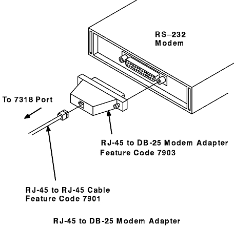
Most modems use DB-25 connectors. Use an RJ-45 to DB-25 modem adapter (Feature Code 7903) when attaching a modem to one of the 7318 serial ports. The RJ-45 to DB-25 Modem Adapter figure depicts the proper configuration for adapting from an RJ-45 plug to a DB-25 port.
Note: This configuration assumes your modem does not require DSR and RI. If it does, use the buddy-mode adapter and cabling. Refer to "Configuring Buddy Mode" for information on buddy mode.
Transmission concerns for modems are similar to those of terminals. Refer to "Installing a Terminal with Defaults" and "Data Transmission" for more information on these topics. Data transmission involves:
Data rate is the speed at which data travels between the modem and computer, measured in bits per second. To successfully transmit data, both devices must transmit at the same data rate; otherwise you may get garbled data or no data at all.
When you use modems in conjunction with the 7318, you may deal with as many as three data rates:
With current modems, these rates are not necessarily the same.
The 7318 supports baud rate cycling; that is, it has the capability to step through different baud rates when negotiating a connection.
You can configure the data rate between the 7318 and the modem in one of two ways:
You should set the 7318-to-modem data rate to a fixed rate. This eliminates one potential source of errors. When using a fixed rate, flow control must be operating properly in both directions.
There are two instances when you may have to configure the modem to dynamically set the data rate:
Historically, older modems transmitted data at the same rate at which they sent data over the phone wire. UNIX was unable to determine the rate over a phone wire; therefore UNIX had to be configurable for a different rate.
Some Hayes and Hayes-compatible modems automatically set their data rate based on AT commands. Though AT commands are normally used for dial-out operations, you can explicitly send AT commands to the modem by directly connecting the modem. In this case, the modem sets its rate to the host's rate.
The modem controls the data rate sent over the wire. For example, a 2400-baud modem can send data at a maximum rate of 2400 baud. Current modems, however, negotiate the transmit data speed. This speed can be a function of the receiving modem or the line conditions. Furthermore, modems with V.42 or V.42bis capability implement compression on the data they transmit.
This means they can effectively send data at a higher rate than their basic rate when viewed from the 7318's point of view. Because of these variables, you should set the modem to the fastest speed the modem supports. Use flow control to manage the rate compensation.
The remote side of the connection faces the same data rate concerns as the local side, that is, the data rate between the 7318 and modem, and the data rate over the phone wire. Just because you use 9600 baud on one end does not necessarily mean the other end is also using 9600 baud.
Parity is a coding scheme for checking the validity of data characters. An extra bit transmitted with each character indicates whether the sum of the other bits in the character is even or odd.
For a modem, parity is not as important as it is for other devices, such as terminals. Modems use an error correction and detection scheme that is more sophisticated than parity on the phone line. Also, data errors are less likely on the short cable typically used between a modem and the 7318.
The parity setting on the AIX host connected to the 7318 must match the parity setting of the device to which you are speaking. The modem transparently replicates the parity through the phone system, so the settings on both sides must agree.
Stop bits delineate the end of a character in the data stream. Use one stop bit unless the device requires otherwise.
Flow control paces the data transmission so that the receiver has a chance to process all of the incoming characters before the transmitter sends additional data.
For modems, flow control can occur in three places:
Although you can use either hardware or software flow control between the 7318 and a modem, you should use hardware flow control. This leaves the Ctrl-S and Ctrl-Q key sequences available to applications, file transfers, and to users for managing screen data.
Modems use a form of flow control between themselves. This is a function of modem standards and does not require you to set any parameters.
Although you can use either hardware or software flow control between the modem and a terminal, you should use hardware flow control. This leaves the Ctrl-S and Ctrl-Q key sequences available to applications, and to you for managing screen data. If you communicate with another computer, using an internal modem, this is not an issue.
You can configure a modem for XON/XOFF flow control. You should use software flow control only when your cabling or modem cannot support the modem control signals for hardware flow control.
Software flow control prohibits the use of the Ctrl-S and Ctrl-Q key sequences from the keyboard, because the system confuses the user's Ctrl-S and Ctrl-Q key sequence with those issued by the modem.
Note: Software flow control should not be used on interfaces performing UUCP transfers. UUCP can send binary data that includes Ctrl-S and Ctrl-Q characters in the data.
If the modem is closer than 150 ft to the 7318, slew rate is not a consideration and should be set to the default. If the modem is farther than 150 ft from the 7318, refer to "Setting the Slew Rate" to change the slew rate to the appropriate setting. Refer to "Data Transmission" for more general information.
Two common EIA 232 signals not provided on the normal port pinouts are DSR and RI. For most applications today, these signals are not used. However, for those applications that do require these signals, the 7318 provides buddy mode.
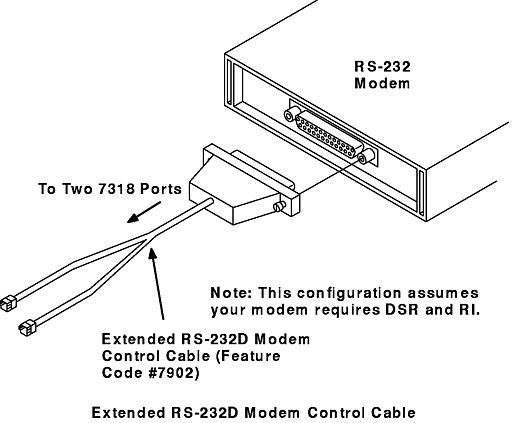
In buddy mode, two adjacent ports are paired to supply the additional DSR and RI signals. The ports must be an even-numbered port and the next-higher odd-numbered port (for example, 0 and 1, or 8 and 9). Buddy mode redefines the pins on the the two ports to provide DSR and RI. The two ports become a single, logical port, which is configured on a port-by-port basis.
The Extended EIA 232D Modem Control cable must be used to connect two RJ-45 connectors to a single DB-25 connector (Feature Code 7902). Refer to the Extended EIA 232D Modem Control Cable figure for a graphic illustration.
Refer to "Connector Pinouts" for details on RS-423, modem, and extended EIA 232D modem control pinouts.
The following information explains the SMIT steps used to configure buddy mode for the 7318.
You must have root user authority.
Note: Configure a tty for the even-numbered port only.
Hardware flow control requires a cable that uses the modem pinout shown in "Connector Pinouts". If you use a cable with only send and receive connected, hardware flow control will not work.
To enable hardware flow control:
stty add rtsand
stty add dtr
The following procedure describes how to enable hardware flow control for AIX Version 4.
Note: If all flow control on a 7318 P10 port is disabled, unpredictable results can occur. Large amounts of data throughput can overflow the P10 internal buffers. Disabling flow control is not recommended.
The 7318 Model P10 has the unique ability to be shared by more than one system. Sharing a Model P10 between hosts can be done in two ways. First, individual ports can be directed to separate hosts. Second, individual port's sessions can be directed to separate hosts. In the first case, each of 16 users could access a different host from the same 7318. In the second case, an individual port or user can access a different host on each of its seven sessions.
The following information describes how to configure a host for a port-to-host type of connection.
This procedure assumes that the Model P10 is already configured with all ports on one host, the load host. If not, take the steps necessary to configure all ports on the load host. Make certain that all ports are operational to the load host before configuring additional hosts.
Ensure that the host's internal network number in the /etc/netware/NPSConfig file is unique on the network.
Although it is possible to select to load from the second host, you should not load from two hosts unless it is required for availability reasons. Loading the 7318 from two hosts will complicate network administration.
The following information describes how to configure a host for a session-to-host type of connection.
A 7318 Model P10 port with six virtual tty devices has a total of seven sessions, numbered 0 through 6. When virtual tty devices are created, they are suffixed with a letter indicating which session they are associated with. The following table shows the association among seven sessions for port 0 for each of two hosts.
| 7318 Port/Device/Session Association | ||||
| Host | Session 0 | Session 1 | Session 2 . . . | Session 6 |
| Host1 Device Names | tty0 | tty0a | tty0b | tty0f |
| Host2 Device Names | tty32 | tty32a | tty32b | tty32f |
Because session 0 on this port can only be associated with a single host, only one of the tty devices in the first column (Host1:tty0, Host2:tty32) should be enabled. Enabling more than one tty device on a port/session causes unpredictable results. You should enable either Host1:tty0 and Host2:tty32a or Host1:tty0a and Host2:tty32 to prevent a conflict. The unused devices and sessions remain present but nonfunctional.
This procedure assumes that the Model P10 port is already configured with multiple sessions on one host, the load host. If not, take the steps necessary to configure the port with all seven virtual ttys on the load host. Make certain that all sessions are operational to the load host before proceeding to configure additional hosts. To validate all sessions, enable the tty and virtual ttys and toggle to them using hot keys.
Ensure that the host's internal network number within the /etc/netware/NPSConfig file is unique on the network.
Although it is possible to select to load from this second host, you should not load from two hosts unless it is required for availability reasons. Loading the 7318 from two hosts can complicate network administration.
Select None in the Autogenerated TTY Devices field unless all 16 of the 7318 ports will have sessions shared by these two hosts. If you select to autogenerate ttys, advance to step 4.
The following information describes the necessary steps for configuring SLIP on a tty.
Steps 7-12 apply to AIX Version 3.2.5 systems only:
stty get < /dev/P10TTYIf xon is one of the outputs on the stack, issue the following command:
stty del xon < /dev/P10TTY
IPAddress   LocalHostName

IPAddress   RemoteHostName
The name you assign should be unique. In other words, if the Ethernet interface on the local host is already assigned the name local , assign the SLIP interface a name such as local_slip .
Direct TTY - ModemBaudRate directIf you are configuring SLIP over a null modem cable. The TTY parameter is the tty specified in step 3.
slattach TTY ModemBaudRateThe TTY parameter is the tty specified in step 3.
slattach TTY ModemBaudRate ' "" AT OK ATDT555-1234 CONNECT "" 'The meaning of this command is: Use the tty specified by the TTY parameter at ModemBaudRate baud. Send AT to the modem. The modem should respond with OK . Dial the phone number 555-1234 . The modem should respond with CONNECT .
slattach TTYThe TTY parameter is the tty specified in step 3.
If both tests succeed, the SLIP connection is ready for use. If not, return to step 1 and verify that the configuration on both the local and remote hosts is correct.
The following information describes the 7318 HA feature, which can be used with High-Availability Cluster Multi-Processing (HACMP) servers. HACMP enables the creation of a cluster of loosely coupled systems.
The Internet Protocol Exchange (IPX) version of the High-Availability (HA) feature of the 7318 can be used with a HACMP/6000 cluster environment. When there is a redundant network, this feature allows the 7318 to recover from a network failure.
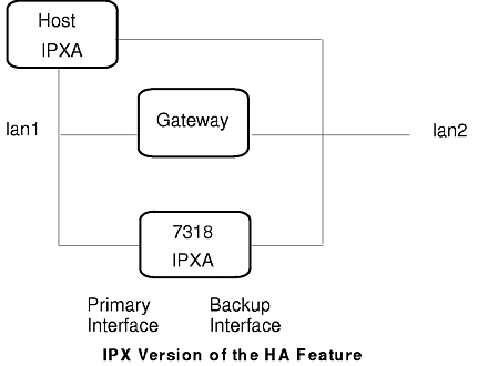
The HA feature is designed to allow a 7318 to physically attach to two distinct local area networks (LANs), using both its 10BaseT and AUI port connectors. Once attached, the 7318 will be given the address of a host or hosts that will determine which network to use.
The 7318 will come online and automatically switch to the interface configured as the primary interface. It will then begin to "ping" the host. As long as those pings are returned, the 7318 will remain on that Ethernet. If, however, the pings stop being returned, the 7318 will switch (after a length of time) to the backup interface. It will then try to ping the host again. If this succeeds, the 7318 will stay on that port. If it fails immediately, or after some amount of time, the 7318 will switch back to primary port and stay there until a ping is returned.
The HA feature is enabled by editing a default configuration file, supplied in the /usr/lib/cns directory. For the Model P10, this configuration file enables the HA feature and multiple sessions. "Configuring the High Availability Environment for the Model P10" details the steps to edit the configuration file.
The IPX version of the HA feature uses an IPX echo packet to determine if the host is online. In the IPX case, there is one IPX address for the 7318 and one for the host.
The following definitions are important in understanding the IPX version of the HA feature:
The 7318 initializes on the primary interface when the HA feature is enabled. Once started, the HA module will "ping" the primary host address using the IPX protocol at a rate determined by the PingingInterval entry. If the ping is not returned, the Switch to Backup timer will start. If that timer expires without receiving any ping response, the HA module will switch the interface to the backup interface.
Once again, it will ping the backup host. If the ping is not returned, the Switch to Primary timer will be started. If that timer expires without receiving any ping response, the HA module will switch the interface back to the primary interface. At this point, the HA module will again start pinging the primary host.
However, in this state, the 7318 will stay on the primary interface until ping responses are received (for example, the interface will not keep switching in the case where there is not response from either port). Once a ping response is received in this state, the HA module resets and returns to its initial state where an absence of ping response will again cause the interface to switch.
Note: In the HA mode, the 7318 will not respond to physical level information from the LAN port. The decision to switch the interface is based only on the ping response from the respective host.
There are two sections in the configuration file which relate to the HA feature, the [HighAvail] section and the [IPX] section, and an optional section, [SPX]. The [HighAvail] section enables and configures the HA feature. The [IPX] section specifies an internal network number so that two distinct networks can be configured.
The IPX Version of the HA Feature figure graphically shows the layout of a 7318 attached to two separate IPX interfaces.
The [HighAvail] section contains the following entries:
Note: Do not configure both primary and backup interfaces to be the same address.
If the high-availability option is being used, and the Internet Packet Exchange (IPX) protocol is being used to ping the host, the 7318 IPX addressing must be changed to allow for handling connection to two different LANs. To do this, an internal network address must be specified for the 7318 (this is similar to the host). The [IPX] section contains the following entry:
The [SPX] section contains the following entries:
Configuring the HA feature involves editing the default configuration file and uncommenting appropriate lines.
You must have root user authority.
cp /usr/lib/cns/p10.cfg /usr/lib/cns/7318EtherAddress.cfgwhere the 7318EtherAddress.cfg parameter specifies the Ethernet hardware address of the 7318 to be configured for HA.
[HighAvail]
enable=0

;addressType=ipx

;primaryhost=00101492.000000000001
;backuphost=00101492.000000000001

;Timeouts in seconds
;switchToBackup=90
;switchToPrimary=90
;pingingInterval=20

;The following interfaces should be set to 10BaseT or AUI.
;The BackupInterface should be the opposite of the primary.
;primaryInterface=10baseT
;backupInterface=AUI

[IPX]
;The internal network is only used when HighAvail is enabled for ipx.
;internalNet=01020304:00406E000001

[SPX]
;If no data and no keepalives are received in idleTimeout seconds,
;the link will drop.
;idleTimeout=15

;The following interval specifies the time between keepalive messages.
;These are used to keep the link alive when no data is being exchanged.
;The idleTimeout should be at least twice the idleInterval value.
;idleInterval=7