The 7318 uses Ethernet to talk to hosts and other devices. Ethernet can be very simple or relatively complicated depending on the network. You do not need to know anything about Ethernet to install the 7318, using the simplified installation procedure. You may, however, make better use of the 7318 if you understand the features and limitations of Ethernet.
Ethernet is logical communication protocol that permits multiple devices to talk to each other over a variety of physical media. This logical protocol is called Carrier Sense Multiple Access with Collision Detection (CSMA/CD).
CSMA/CD is a broadcast mechanism where one station speaks while all others listen. When two stations try to speak at the same time, a collision takes place. With CSMA/CD, both stations detect the collision, back off, and retry later. In practice, collisions rarely happen.
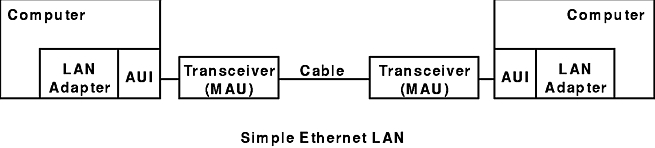
A simple form of an Ethernet local area network (LAN) is illustrated by the Simple Ethernet LAN figure.
The LAN adapter provides the interface between the computer and the Ethernet. The transceiver, also called a medium attachment unit (MAU), provides the physical interface to the LAN medium. The interface between the LAN adapter and transceiver is the adapter unit interface (AUI). This interface has a standard connector (DB-15 with slide latches) and electrical characteristics. The Ethernet medium is a cable. The type of cable depends on the type of Ethernet.
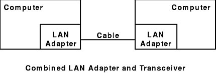
In many cases, a single electronics board combines the LAN adapter and the transceiver. The 7318 includes a transceiver for 10BaseT Ethernet on its main electronics board along with an integrated LAN adapter. In this case, the system looks like the Combined LAN Adapter and Transceiver figure.
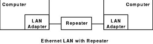
There is a distance limit on the cable between two transceivers. This limit depends on the type of Ethernet. A repeater amplifies and retimes the Ethernet signals enabling transmission over longer distances. A repeater can have more than two ports. A multiple port repeater is commonly called a hub, particularly when used with 10BaseT. The Ethernet LAN with Repeater figure depicts a network using a repeater with two ports.
Constraints are guidelines specified by Ethernet architects to guarantee proper operation at a particular installation. You can guarantee proper operation at your installation by not violating any of the constraints. One indicator of constraint violation is a higher than normal error rate. Because of the error recovery mechanisms inherent in communication protocols, a high error rate is often only apparent to the user as lower performance.
There are two types of constraints on Ethernet:
There are three limitations on a physical medium:
These particular limitations ensure the integrity of the signal between any two stations regardless of Ethernet implementation.
Architectural constraints derive from timing parameters of the CSMA/CD protocol. For the collision detection and recovery mechanism to operate properly, the time interval between when two LAN adapters recognize a collision is bound. As a result, the overall size of the system is bound by the propagation time of the signals over the longest path.
There are three types of Ethernet:
| 10BaseT | Uses unshielded twisted-pair cables as its transmission medium. It depends upon an active hub to resolve collisions between stations trying to talk at the same time. |
| 10Base2 | Uses inexpensive coaxial cable as its transmission medium. It depends upon transceiver logic in the host adapter to resolve collisions. |
| 10Base5 | Uses a special double-shielded coaxial cable as its transmission medium. It depends on an external transceiver to resolve collisions. |
The 7318 works with any of the Ethernet types but works optimally with 10BaseT. 10BaseT is recommended for all new installations because of its ease of maintenance.
10BaseT uses a star topology. Each of the communication devices connects to a centrally located hub that implements the CSMA/CD protocol. A star topology Ethernet using twisted-pair is easier to maintain than coaxial types of Ethernet because:
For example, one of the simplest diagnostic tools is the link integrity indicator. A link integrity indicator is a light on the hub and adapter cards that remains on as long as the link integrity signal is not compromised. A hub and its devices constantly transmit a link integrity signal. This is a simple way to verify a proper physical connection. The network status light on the front of the 7318 indicates link integrity when 10BaseT is in use.
In a more sophisticated implementation, an intelligent hub can provide link integrity status to network management software. This eliminates the need to go to the hub or device to see the status of the indicator light.
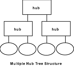
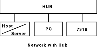
A 7318 can act as a one port hub or as a client to a hub (similar to PCs or servers). A normal 10BaseT hub provides a fixed number of ports, such as 16. You can expand the total number of ports on a network by attaching multiple hubs together. When attaching hubs together, you can use twisted-pair (10BaseT technology) or coaxial (10Base2 or 10Base5 technology) cable. When connecting multiple hubs, the network is usually organized in a tree, as illustrated in the Multiple Hub Tree Structure figure.
The Network with Hub figure illustrates a typical way to set up a network with a hub.
The maximum cable length between any two end points on a 10BaseT Ethernet is 100 meters (end points are active devices, such as host adapters, transceivers, or hubs). An end point can be either a 10BaseT transceiver or a hub. This 100-meter limitation assumes that you are using level 3 cable and a limited number of interconnects. Interconnects include plug-in sockets or punch-down blocks. Using inferior cable or an excessive number of interconnects reduces the effective length.
There is a maximum of four repeaters between any two stations. A 10BaseT hub counts as a repeater.
To install a 7318 as a client to a 10BaseT hub:
Note: In this configuration, the 7318 acts as a peer to other devices on the LAN, such as PCs and servers.
| Troubleshooting 10BaseT | |
|---|---|
| Symptom | Action |
| The link integrity indicator is off on one or both sides of the connection. | Verify the cable. Verify the pinout of the cable. |
| The link integrity indicator is on for both devices, but the devices still don't communicate. | Verify the quality of the cable. |
| The transfer rate is very slow. | Verify the quality of the cable. Verify the integrity of the interconnect. |
Verify that the devices are firmly plugged in. Verify that the ends of the same cable are securely in the jack.
Check that you are using a straight-through cable. A normal 10BaseT is a straight-through cable. This means that pin 1 at one end of the cable connects to pin 1 at the other end. Similarly pin 2 connects to pin 2, and so on for all connector pins.
Check the cable pairs. The cable pairs within the twisted pair must also connect properly. Connector pins 1 and 2 attach to one pair while pins 4 and 6 connect to the other.
Check for any occurrence of flat silver satin conductor wire. This wire is commonly sold for use with telephones and is not appropriate for 10BaseT installation due to incorrect electrical characteristics.
All of the cables in your 10BaseT Ethernet, including jumper cables, must be LAN-grade cables (Level 3 ATP). Even a short length of silver satin cable can cause a connection malfunction.
A continuity tester may show that a connection is electrically correct. However, in terms of a transmission, the connection has excessive impedance mismatches. These impedance mismatches result from discontinuity. A cable splice or a plug in socket are two items that cause discontinuity. Each occurrence degrades the signal.
You can use a time domain reflectometer (TDR) to test for discontinuity. The TDR identifies each occurrence by indicating the distance from the end of the cable to the discontinuity.
10Base2 is a simplified form of the original Ethernet that uses T-connectors in place of the original Ethernet tapped-style transceivers. This form of Ethernet is inexpensive and easy to install for small networks. On a larger network, thin coaxial is difficult to maintain. In a typical 10Base2 installation, one electronics board contains both the transceiver and the LAN adapter.
The 7318 does not include a 10Base2 transceiver as part of the base unit. You can purchase an optional external 10Base2 transceiver for use with the 7318 from your reseller.
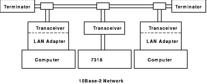
The 10Base2 Network figure depicts a sample 10Base2 network.
10Base2 is a linear or bus topology that extends from device to device throughout a network. Each end of the bus must be capped off with a terminator. Between these terminated end points, you can attach up to four repeaters. The cable must be either RG58A/U or RG58C/U coaxial cable.
Most transceivers contain a switch to enable or disable a function called SQE heartbeat. When using the transceiver with the 7318, you should set this switch to enable SQE heartbeat. This should be the default setting. SQE heartbeat sends a special signal to the 7318 that enables it to detect when it has successfully transmitted a packet on the Ethernet. If this function is disabled, the 7318 will report transmission errors.
The maximum segment length for a 10Base2 Ethernet is 185 meters or 600 feet. The maximum number of stations for each segment is 30. You can use up to four repeaters. When you use four repeaters, only three of the five segments can have taps. The remaining two segments must be direct links. The minimum distance between stations is 0.6 meters or 1.5 feet.
To install the 7318 into an existing 10Base2 network:
Note: The network must be down while you are plugging in the new T-connector and cable segment. You can minimize network downtime by having all the cables and connectors ready and in place before you open the existing cable. You can attach the cable to the transceiver after the network is back in operation.
| Troubleshooting 10Base2 | |
| Symptom | Action |
| No stations talking. | Verify cable termination. Split the network into segments to isolate problems. |
| One station doesn't talk. | Verify the Ethernet adapter in the station. Replace the T-connector. |
| Whole network slow. | Split the network into segments to isolate problems. Verify cable termination. |
| One station slow. | Verify the Ethernet adapter in the station. |
Verify that a cable terminator is attached to both ends of the cable. If the network still does not work, remove the terminator from one end and use an ohmmeter to measure the resistance between the center tap of the cable and the shield. The resistance should be 50 ohms if the terminator at the opposite end is correct. Replace the terminator and repeat the experiment at the opposite end.
Somewhere near the middle of the cable, remove one cable end from the T-connector, and replace it with a terminator. Test the new shorter segment. If it works, replace the cable, and put a terminator on the opposite side of the T-connector. Now test the other segment. If either side of the T-connector fails, focus on that segment. Keep repeating this experiment, making the defective segment smaller and smaller, until you isolate a defective cable, node, or T-connector.
T-connectors are defective more often than you might think. If you have narrowed the problem to a segment with a single T-connector, try replacing the T-connector.
If you remove the T-connector from an Ethernet adapter or transceiver and everything else on the network works, try replacing the isolated Ethernet adapter or transceiver.
10Base5 is the original form of Ethernet. It uses a special double-shielded coaxial cable. Transceivers are separate from the Ethernet adapters and tap into the cable. You can attach the AUI port on the 7318 to a transceiver tapped into the Ethernet cable, using an AUI cable.
10Base5 is a linear or bus topology that extends through a building, usually in the ceiling. Devices attach to the transceivers tapped into the cable with an AUI cable. Like 10Base2, a 10Base5 network must be terminated at both ends, or the network will not function.
10Base5 requires a special coaxial cable designed exclusively for Ethernet and readily identifiable by its yellow jacket. A variant of this cable is available with a fire-retardant jacket for use in plenums. This variant has an orange jacket. AUI cables are constructed from shielded coaxial cable.
10Base5 is not recommended for new installations. It is significantly more expensive than either 10BaseT or 10Base2 and has similar maintenance problems to 10Base2. It does have one advantage: individual segments can be up to 500 meters (1640 feet) long.
The maximum segment length for a 10Base5 Ethernet is 500 meters (1640 feet). The maximum number of stations per segment is 100. You can extend segments with up to 4 repeaters, but only three of the segments can have taps on them. The other two segments must be direct links. AUI cables can be up to 50 meters (164 feet) long.
To install a 7318 into an existing 10Base5 Ethernet:
| Troubleshooting 10Base5 | |
|---|---|
| Symptom | Action |
| No stations talking. | Verify cable termination. Split the network into segments to isolate problems. |
| One station doesn't talk. | Verify the Ethernet adapter in the station. Replace the transceiver. |
| Whole network slow. | Split the network into segments to isolate problems. Verify cable termination. |
| One station slow. | Verify the Ethernet adapter in the station. Replace the transceiver. |
Verify that a cable terminator is attached to both ends of the cable. If the network does not work, remove the terminator from one end and use an ohmmeter to measure the resistance between the center tap of the cable and the shield. The resistance should be 50 ohms if the terminator at the opposite end is correct. Replace the terminator you removed, and repeat the experiment at the opposite end.
Somewhere near the middle of the cable, remove one cable end from the transceiver and replace it with a terminator. Test the new shorter segment. If it works, replace the cable and put a terminator on the opposite side of the transceiver. Now test the other segment. If either side of the transceiver fails the test, focus on that segment. Keep repeating the experiment, making the defective segment smaller and smaller, until you isolate a defective cable, node, or transceiver.
If you have a tapped transceiver, you can simply remove it from the cable. Otherwise, unscrew the coaxial connectors, and replace the transceiver with another one.
If you remove the AUI cable from an Ethernet adapter and everything else on the network works, try replacing the isolated Ethernet adapter or transceiver.