[ Previous |
Next |
Contents |
Home |
Search ]
AIX Versions 3.2 and 4 Asynchronous Communications Guide
7318 Troubleshooting
The following troubleshooting information is divided into the following areas:
The troubleshooting information is intended as a guide to help in problem isolation. Some of this information assumes more technical knowledge of the devices or applications involved.
One approach to isolation is substituting known good components or devices for suspect ones, including another 7318 if it is available. This approach is not included in these isolation procedures because the availability of hardware at the installation site is unknown.
In all cases that ask you to check the cabling or devices, you may replace cables, adapters, devices, null modems, and so forth to help isolate the problem.
To use this section most effectively:
- Select the area that covers the problem.
- Follow the recommended actions and procedures.
System Checkout Using the Standalone BIOS Console
The following procedure guides you through a full checkout of the 7318, providing a quick test to tell if the 7318 hardware needs to be replaced. The procedure uses the 7318 BIOS console commands to run diagnostic wrap tests on all of the ports on the 7318. If a failure is detected, no Service Request number is generated and you must replace the unit.
Note: Customer Engineers should run this procedure for 7318 FRU isolation. If the 7318 hardware passes this checkout, use the other troubleshooting information and procedures in this section to isolate the problem. The problem may originate from a wide spectrum of hardware and software variables including devices, cables, networks, and configuration parameters.
Prerequisites
- An ASCII terminal must be available for the BIOS console.
- All ports on the 7318 must be inactive (all users logged off and all applications stopped).
- Establish a BIOS console. Refer to "BIOS Console Operation" and "7318 Diagnostics" for a description of the BIOS console and the set, show, and diag commands. To request a BIOS console, perform the following steps:
- Unplug the 7318 power cord.
- Connect an ASCII terminal to any one of the 7318 serial ports.
- Set the terminal to 9600 baud, 8 data bits, one stop bit, no parity.
- Plug in the 7318 power cord.
- Type #
(pound sign, ASCII 0x23) continually until the console echoes ####
(four pound signs).
- The BIOS should respond with a console header and the >
(redirect symbol) prompt.
- Enter password privilege mode, using the admin command. Refer to "admin Command" for information on how to use the admin command.
Run the Ethernet Port Wrap
- Remove all the Ethernet cable(s) from the 7318, noting the ports (A,T, T-X, I, O) they are connected to for later reattachment.
Note: If the daisy-chain cable is not removed when doing LAN diagnostics, the diagnostic will fail along with any further LAN diagnostics. A reboot of the 7318 is needed to clear this failure.
- Attach the AUI Ethernet wrap plug (Part Number 71F1167) supplied with your system to the AUI Ethernet port (labeled "A" on the back panel).
- Run the Ethernet port wrap test by entering the following commands, noting any error indications that appear:
set device lan
set interface 2
diag -w
- Remove the AUI Ethernet wrap plug from the AUI Ethernet port.
- Attach the RJ-45 Ethernet wrap plug (Part Number 00G2380) supplied with the 7318 to the T Ethernet port.
- Run the Ethernet port wrap test by entering:
set device lan
set interface 1
diag -w
- Remove the RJ-45 Ethernet wrap plug from the T Ethernet port.
- Attach the RJ-45 Ethernet wrap plug supplied with the 7318 to the T-X Ethernet port.
- Run the Ethernet port wrap test by entering:
set device lan
set interface 1
diag -w
- Remove the RJ-45 Ethernet wrap plug from the T-X Ethernet port.
- Attach the DB-9 daisy-chain wrap plug (Part Number 65G2382 male) to the O port. This wrap plug is only available with Feature Code 7909. If not used, skip to step 7.
- Run the Ethernet port wrap test by entering:
set device lan
set interface 0
diag -u
- Remove the wrap plug from the O port.
- Attach the DB-9 daisy-chain wrap plug (Part Number 65G2407 female) to the I port. This wrap plug is only available with Feature Code 7909. If not used, skip to step 7.
- Run the Ethernet port wrap test by entering:
set device lan
set interface 0
diag -u
- Remove the wrap plug from the I port.
- Reattach all Ethernet cables to the 7318.
- If there were any error indications, then this procedure has failed. Stop problem isolation and replace the 7318.
Run the Parallel Port Wrap
Remove the parallel port cable or cables from the 7318 connectors (labeled P1 and P2) noting the ports they are connected to for later reattachment.
- Attach the parallel port wrap cable (Part Number 65G2381) supplied with your 7318 to the parallel ports.
- Run the parallel port wrap test by entering the following commands, noting any error indications that appear:
set device lpt1
diag -m

set device lpt2
diag -m
- Remove the parallel port wrap cable and reattach the parallel port device cables.
- If there were any error indications, then this procedure has failed. Stop problem isolation and replace the 7318.
Run the Serial Port Wrap
Run the serial port wrap for each serial port, COM00 through COM15 (other than the BIOS console port), on the 7318. Perform the following steps:
- Remove the cable from the RJ-45 connector for the serial port to be tested.
- Install the serial port wrap plug (Part Number 65G2350) supplied with the 7318.
- Run the serial port wrap test by entering the following commands, noting any error indications that appear. Change the device identifier, com00
, to match the port being tested.
set device com00
diag -w
- Remove the serial port wrap plug and reattach the serial cable that was connected to the port.
- If there were any error indications, then this procedure has failed. Stop problem isolation and replace the 7318.
- Remove the BIOS console terminal and reattach the serial cable for the port as it was prior to running the procedure in "System Checkout Using the Standalone BIOS Console".
If any of the diagnostics indicate a failure, replace the 7318.
If there were no error indications, then this procedure has passed. Exit this procedure. If you were referred to this procedure from another procedure, return to the original procedure and continue problem isolation. If you have performed no other diagnostic procedures, load the 7318 from a host on which the 7318 software is installed. Refer to "Front Panel Status Lights (Startup and Loading)" if the load is unsuccessful.
System Checkout Using the Service Aid
The following procedure guides you through the operation of the 7318 Service Aid. It performs wrap tests on the 7318 parallel and serial ports, providing a reliable test of whether the hardware is operational. If the Service Aid detects a failure, it may be caused by many different parts of the system. In this case, perform the "System Checkout Using the Standalone BIOS Console" for further problem isolation.
Note: The Service Aid can only be run from a system on which the software is installed and the devices and ports to be tested have been configured. For Model S20 units, the serial ports may not have P10-style ports configured on the system where the 7318 software support is installed. If there are no P10-style ports configured on the Model S20, the Service Aid will not be operational.
Prerequisites
You must have root user authority to run the Service Aid.
Note: Running some of the diagnostics automatically logs off any users on the 7318; thus, the diagnostics should be used carefully.
Procedure
- To run the Service Aid, issue the diag command from the AIX command line.
- From the first panel, select Service Aids.
- From the next panel, select IBM 7318 ComNet Server Service Aid.
- Select whether you want standard tests, which do not require special plugs, or advanced tests, requiring a serial port wrap plug (Part Number 65G2350) or a parallel port wrap cable (Part Number 65G2381). Press Enter.
The diagnostics run unattended and display their results in the diag command window. At the end of the diagnostics, either RESULT:
SUCCESS
or RESULT:
FAILURE
displays. If there is a failure, at least one additional message describing the problem displays. For example, you may also see a message such as Device power-on self-test failed
.
Problems with BIOS Console Communication
If you have problems requesting a BIOS console, consider the following symptoms and their possible causes:
| BIOS Console Problems |
|
| Symptom |
Action |
| Console doesn't echo pound sign. |
Verify terminal is cabled correctly. Verify terminal settings (9600/8/1/N). Power-cycle the 7318 and type the pound sign a little later. Try a different serial port. |
| Pound sign garbled. |
Verify terminal settings (9600/8/1/N). |
| No console header message. |
If pound signs echo, try repowering the 7318 and typing the first pound sign faster, (four or more). Try a different serial port. |
| No Ready light within 20 seconds. |
Power-on self-test failed. Replace the unit. |
Terminal is Cabled Correctly
If your terminal has a Data Terminal Equipment (DTE) interface, the cable will require a null modem adapter. The cabling must support pins for Transmit Data (TD), Receive Data (RD), and signal ground (TD REF). Refer to "Connector Pinouts" for more information.
Terminal Settings
Verify that the terminal transmits and receives at 9600 baud, with 8 data bits, 1 stop bit, and no parity. Check the emulation mode of the terminal (if applicable) to be sure that the # (pound sign) key you are pressing corresponds to an ASCII pound sign symbol (0x23).
Power Cycle the 7318
Unplug the 7318 and wait 30 seconds, then plug in the power cord again.
Front Panel Light Status (Startup and Loading)
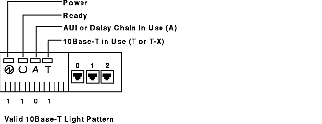
Familiarize yourself with the following symbols, which are used to reference the light patterns:
- 0 indicates the light is off.
- 1 indicates the light is on.
- B indicates the light is blinking.
The Valid 10BaseT Light Pattern figure shows how the preceding symbols correspond to the lights on the front panel. In this situation, the 1 1 0 1 light pattern would signify that the power and the ready light are on, the AUI light is off, and the 10BaseT light is on.
Examine the front panel lights, and match them with the patterns in the following list:
| 0 0 0 0 |
No power to the 7318.
Action: Verify power to the 7318, cycle the power, wait 10 seconds.
- If the light pattern changes, continue to match the new pattern with those shown in the table below. (This should have no effect on other devices attached to the Ethernet.)
Attention: Daisy-chained 7318s will lose their connection if a higher 7318 in the daisy chain is power cycled (for example, power-cycling the second 7318 will end network connection for the third and fourth 7318 in the daisy chain).
- If the light pattern does not change, replace the unit.
|
| 1 0 0 0 |
The power-on self-test appears to detect a fatal error.
Cycle the power, wait 15 seconds. If this pattern persists, replace the 7318. |
| 1 B 0 0 |
Power-on self-test is complete, 7318 search for load host is in progress. (This light pattern is also seen when the BIOS console is active.)
Wait 30 seconds. If lights remain in this state, the 7318 has not found an operational Ethernet interface, or the transceiver attached to the Ethernet port does not support SQE heartbeat. Continue with the steps described below:
- If the transceiver attached to port A does not support SQE heartbeat or if SQE heartbeat is turned off, move to light pattern 1 B 0 1 or 1 B 1 0. Enable SQE heartbeat if the transceiver supports it.
- If the 7318 is part of a 7318 daisy chain, then:
- Check that you cabled the 7318s correctly and power off all 7318s in the daisy chain. Power on the daisy-chained 7318s starting with the first. Refer to "Attaching Multiple 7318s" for information on daisy-chain configuration.
- Remove the 7318 from the daisy-chain, and ensure it downloads correctly by itself on the Ethernet.
If the independent download fails, then continue problem isolation with step 3.
If the independent download succeeds, run the procedure described in "System Checkout Using the Standalone BIOS Console" for each 7318 in the daisy-chain, looking for an in/out port (I and O port) failure.
- Call your next level of support.
- Check for an Ethernet media problem. Refer to your Ethernet setup/installation guide to check for incorrect cabling, bad termination of the Ethernet, loose connectors, bad cable, down routers, and so forth.
- Check for an Ethernet interface problem on the host. Refer to your Ethernet setup/installation documentation and look for incorrect definition of the Ethernet interface, host addresses and subnets, BOOTP configuration (Model S20), Model P10 SMIT panels, and so forth.
- Check for a host or 7318 configuration problem. Refer to your 7318 installation and configuration documentation, and look for correct setting of network addresses, Model P10 SMIT panels, configuration file setup, and so forth.
- Other things to try:
- On any host where the 7318 software is installed: the cnsview -c "explore" command should display all 7318s that are powered up and reachable from the host.
- On any host where the 7318 software is installed: the cnsview -c "ipxping EthernetAddress" command should display the following response:
EthernetAddress is alive
where the EthernetAddress
parameter specifies the Ethernet hardware address on the back of the 7318.
- Attach a BIOS console and issue the load command. The console will display log messages as the load sequence progresses, allowing you to check for the following:
- Network addresses
- Name resolution
- Service advertisement and response
- Bootp reply
- Download image path and file name
- Ethernet frametype
- Configuration file path and file name.
The degree of progress made in these steps may also indicate where the problem is. Refer to "BIOS Console Operation" and "Logging During Load" for more details.
- Stop and restart the cnsview daemon and IPX protocol stack by issuing:
To STOP:
cnsview -c "daemon stop"
/usr/lpp/netware/bin/stopnps
To START:
/usr/lpp/netware/bin/startnps
cnsview -c "daemon start"
- Run the procedure described in "System Checkout Using Standalone BIOS Diagnostics Procedure".
- Call your next level of support.
|
1 B 0 1
1 B 1 0 |
Load image and configuration file load in progress.
- Check for an Ethernet interface problem on the host. Refer to your Ethernet setup/installation documentation and look for incorrect definition of the Ethernet interface, host addresses and subnets, BOOTP configuration (Model S20), Model P10 SMIT panels, and so forth.
- Check for a host or 7318 configuration problem. Refer to your 7318 installation and configuration documentation, and look for correct setting of network addresses, Model P10 SMIT panels, configuration file setup, and so forth.
- Other things to try:
- On any host where the 7318 software licensed program product is installed: the cnsview -c "explore" command should display all 7318s that are powered up and reachable from the host.
- On any host where the 7318 software licensed program product is installed: the cnsview -c "ipxping EthernetAddress" command should display the following response:
EthernetAddress is alive
where the EthernetAddress
parameter specifies the Ethernet hardware address on the back of the 7318.
- Attach a BIOS console and issue the load command. The console will display log messages as the load sequence progresses, allowing you to check for the following:
- Network addresses
- Name resolution
- Service advertisement and response
- BOOTP reply
- Download image path and file name
- Ethernet frametype
- Configuration file path and file name.
The degree of progress made in these steps may also indicate where the problem is. Refer to "BIOS Console Operation" and "Logging During Load" for more details.
- Run the procedure described in "System Checkout Using the Standalone BIOS Console".
- Call your next level of support.
|
| 1 1 0 0 |
The 7318 has successfully downloaded. The 1 1 0 0 light pattern is valid for:
- Configuration file processing (five minutes maximum).
- Ethernet transceivers that do not support the SQE heartbeat.
If after five minutes the 7318 is still not operational:
- Link integrity has been lost. Check the Ethernet connections.
- Run the procedure described in "System Checkout Using the Standalone BIOS Console".
- Call the next level of support.
|
1 0 1 0
1 0 0 1 |
- Upload in progress. Refer to "BIOS Upload Sequence" for details on the BIOS upload.
- Call the next level of support.
|
1 1 1 0
1 1 0 1 |
The 7318 is loaded and operational. Problems that persist with this light pattern are likely to be host configuration problems.
- Check configuration file and Model P10 SMIT panels for incorrect configuration information.
- Call next level of support.
|
| 1 1 1 1 |
Light test.
If temporary, none. If solid, replace unit. |
| 0 X X 1 |
Invalid Pattern |
| 0 X 1 X |
Invalid Pattern |
| 0 1 X X |
Invalid Pattern |
| Other |
Invalid Pattern
- If the 7318 fails the power-on light test but otherwise operates normally, replace the 7318 at your discretion.
If the 7318 fails the power-on light test and operates abnormally, run the procedure described in "System Checkout using the Standalone BIOS Console".
- Call the next level of support.
|
| Cycling |
If the 7318 is cycling through patterns:
- Load using the default configuration file.
- Attach a BIOS console and issue the load command. The console will display log messages as the load sequence progresses, allowing you to check for the following:
- Network addresses
- Name resolution
- Service advertisement and response
- BOOTP reply
- Download image path and file name
- Ethernet frametype
- Configuration file path and file name.
The degree of progress made in these steps may also indicate where the problem is. Refer to "BIOS Console Operation" and "Logging During Load" for more details.
- Call the next level of support.
|
Replacing a 7318
The following procedure preserves the TTYx and LPx devices configured for this 7318. If this is a Model S20 with P10-style ports, perform the sequence below on each host on which this 7318 is configured.
Prerequisites
You must have root user authority.
Procedure
- Use the smit ts7318_cs_mnu fast path to access the ComNetServer Server Configuration menu.
- Select Show/Change Configured ComNetServers.
- Select the ComNetServer that was replaced.
- Modify the ComNetServer Ethernet Address field to reflect the Ethernet address of the new ComNetServer.
- Select Do.
- Exit the SMIT interface.
- Modify the bootptab file (etc/bootptab), if necessary, to reflect the new Ethernet address if the 7318 was replaced with a Model S20. This is done from the host where the 7318 boots.
- Rename the customized configuration to reflect the new Ethernet address if there is a customized configuration file for this 7318. This is done from the host where the 7318 boots.
- Update the NVRAM on the new 7318 to match the values on the old unit if the 7318 has customized NVRAM fields. Set these fields using the BIOS console.
Problems with Terminals
| Terminal Problems |
| Symptom |
Action |
| The terminal does not respond. |
Verify the cabling.Verify that the terminal is enabled.Verify the transmission parameters.Run the procedure in "System Checkout Using the Service Aid" (Model P10 ports only). |
| You see garbled characters. |
Verify the transmission parameters. Verify the slew rate. Verify flow control. |
| You see output to the terminal but the keyboard does not function. |
Verify the transmission parameters. Verify the cabling. Run the procedure in "System Checkout Using the Service Aid" (operational for Model P10-style ports only). |
| You see missing or bad cursor addressing. |
Verify the terminal type. Verify flow control. |
| Multiple sessions does not refresh the screen properly on switch. |
Verify the terminal type. |
Cabling
- If you are using a modem control device, type the following from any host on which the 7318 software is installed to check the status modem signals:
cnsview -c "show modem" DeviceName
where the Devicename
parameter specifies the name of the device, such as /dev/tty1. Data Carrier Detect (DCD) and Clear to Send (CTS) should both be 1.
- If your cabling implements all of the EIA 232 signals supported by the 7318 and has EIA 232 standard DB-25 pinout, use the procedure for "System Checkout Using the Standalone BIOS Console, Run the Serial Port Wrap" and the serial port wrap plug supplied with the RS/6000 (part number 6298964) to verify the complete cable path to the serial device.
For Model P10 ports, the 7318 Service Aid Advanced Test may be used rather than the BIOS Console procedure.
Problems with Printers
| Printer Problems |
| Symptom |
Action |
| Serial printer not working. |
Verify printer status. Verify printer enabled and accepting requests. Verify serial cabling. Verify printer model. Verify slew rate. |
| Parallel printer not working. |
Verify printer status. Verify printer enabled and accepting requests. Verify parallel cabling. Verify printer model. |
| Terminal transparent printer not working. |
Verify printer status. Verify printer enabled and accepting requests. Verify serial connection. Verify printer model. Verify that you are only sending ASCII data to the printer. |
| Garbage characters on serial printer. |
Verify serial connection. Verify printer model. Verify slew rate. |
| Garbage characters on parallel printer. |
Verify printer model. |
| Garbage characters on terminal transparent printer. |
Verify terminal to printer connection. Verify printer model. |
| Characters dropped on serial printer. |
Verify flow control. |
| Characters dropped on terminal transparent printer. |
Verify transparent printer rate. |
| Attached terminal of terminal transparent printer stops responding. |
Verify transparent printer rate. |
Note: The procedure described in "System Checkout Using the Service Aid" applies to all of the symptoms in the Printer Problems table.
Printer Status
Check your printer to make sure it is online, does not show an error condition, or is not out of paper.
Printer Enabled and Accepting Requests
- Use the smit qchk fast path to access the Show the Status of Print Jobs screen.
- In AIX Version 3.2.5, select yes in the Show the status of ALL print jobs? field.
- In AIX Version 4, enter an * (asterisk) in the PRINT QUEUE name field to display jobs in all queues.
- Select Do.
- Verify that the Status field for each printer indicates READY
or RUNNING
. Other values may indicate the printer is not working for various reasons (for example, out of paper, cable not attached, out of toner).
- Exit the SMIT interface.
Serial Cabling
- Use the cnsview command to check the status modem signals by entering the following:
cnsview -c "show modem" DeviceName
where the DeviceName
parameter is the name of the device, such as /dev/tty01. CTS and DCD should both be 1.
- If your cabling implements all of the EIA 232 signals supported by the 7318 and has EIA 232 standard DB-25 pinout, use the procedure for "Run the Serial Port Wrap" and the serial port wrap plug supplied with the RS/6000 (part number 6298964) to verify the complete cable path to the serial device.
For Model P10 ports, the 7318 Service Aid Advanced Test may be used rather than the BIOS Console procedure.
- Use an EIA 232 tester plugged into the back of the modem. The modem control line should be asserted, the Data Terminal Ready (DTR) line may flicker, and the TD and RD lines should flicker as data crosses the tester.
Printer Model
To verify the printer/plotter model:
- Use the smit chgprt fast path.
- From the displayed list, select the desired device.
- From the Change/Show Characteristics of a Printer/Plotter menu, verify that the Printer/Plotter type matches the type of printer/plotter you have.
Parallel Cabling
Use the cnsview command to check the printer control signals by entering the following:
cnsview -c "show lptctl" DeviceName
where the DeviceName
parameter specifies the name of the device, such as /dev/lp2.
When the printer is online but not printing, you should see:
selected:   1
peb:        0
error:      0
selection:  1
init:       0
feed:       0
If you do not see these signals, try replacing the printer cable.
Flow Control on a Serial Port
Use the smit chgprt fast path to take you to the Change/Show Characteristics of a Printer/Plotter menu. If your terminal (on AIX Version 3.2.5 systems) is set for XON/XOFF flow control, the XON-XOFF handshaking field should be set to yes. On AIX Version 4 systems, set the FLOW CONTROL to be used field to xon.
If your terminal (on AIX Version 3.2.5 systems) is set for DTR flow control, ensure that the Use DTR communication protocol field is set to yes. On AIX Version 4 systems, set the FLOW CONTROL to be used field to dtr.
Slew Rate
Transparent Printer Rate
Use the smit ts 7318_prt_mnu fast path to verify the transparent printer parameters in the Show/Change Configured ComNetServer Printers dialog.
Problems with Modems
| Modem Problems |
| Symptom |
Action |
| Modem does not answer. |
Verify the cabling. Verify that modem autoanswer is enabled. |
| Modem will not dial out. |
Verify the data rate. Verify the cabling. Verify the flow control. Verify the slew rate. |
| Modem answers with garbled data. |
Verify the data rate. Verify the flow control. Verify the slew rate. |
Note: The procedure described in "System Checkout Using the Service Aid" applies to all of the symptoms in the Modems table.
Cabling
- Use the cnsview command to check the status modem signals by entering the following:
cnsview -c "show modem" DeviceName
where the DeviceName
parameter specifies the name of the device, such as /dev/tty01. CTS should be 1. DCD should be 0 until the modem answers and should be 1 after it answers.
- If your cabling implements all of the EIA 232 signals supported by the 7318 and has EIA 232 standard DB-25 pinout, use the procedure for "System Checkout Using the Standalone BIOS Console, Run the Serial Port Wrap" and the serial port wrap plug supplied with the RS/6000 (part number 6298964) to verify the complete cable path to the serial device.
For Model P10 ports, the 7318 Service Aid Advanced Test may be used rather than the BIOS Console procedure.
- Use an EIA 232 tester plugged into the back of the modem. The modem control lines should be asserted, the DCD line should not be asserted when there is no carrier, and the TD and RD lights should flicker as data crosses the tester.
Modem Autoanswer is Enabled
Verify that the S0 register is not set to zero (disable autoanswer).
Data Rate
If you have configured your modem to use a fixed data rate (recommended), verify that the SMIT setting matches the modem data rate (usually 9600).
Flow Control
To verify flow control settings, perform the following steps:
- Run the smit chgtty fast path.
- Select a TTY from the list that displays.
- On AIX Version 3.2.5 systems only, select Change/Show TTY Program. If you are an AIX Version 4 user, proceed to step 4.
- Scan to the end of the field attributes for the STTY attributes for LOGIN field. You should see ixon and ixoff indicating that the TTY is configured for XON-XOFF handshaking.
- On AIX Version 4 systems only, set the FLOW CONTROL to be used field to xon for XON-XOFF flow control or to rts for RTS/CTS flow control
- On AIX Version 3.2.5 systems only, select Change/Show Hardware Characteristics of a TTY.
- If you set your modem for XON/XOFF flow control, the SMIT dialog should display yes
for XON-XOFF handshaking.
- If you set your modem for RTS/CTS flow control, you should confirm that the port is configured for RTS/CTS flow control.
- Select Do.
- Exit the SMIT interface.
To verify the flow control on a Model S20 port that is not configured as a P10-style port, view the default or customized configuration file for the 7318. Find the [PortNN] subsection that corresponds to the appropriate port. Find the stty
entry and scan the line to find the flow control settings (ixon
, ixoff
).
Slew Rate
To verify the slew rate on a Model P10, see "Slew Rate".
Problems with P10-Mode Remote Ethernet
This section discusses how to troubleshoot typical problems you may have over WAN connections or other routed networks. This section assumes that you have a basic understanding of the BIOS console and other administrative functions in cnsview.
Booting Across a Router Using Undirected IPX Loading
If you have problems getting the 7318 Model P10 to boot over a router, it is likely this is a configuration problem. The best approach for this is to make certain your configuration works locally first. This way you can be sure that your hardware and cabling work. If you can configure the 7318 to boot locally, then just a few parameters must be changed to have the 7318 boot remotely.
- Use the smit ts7318_cs_mnu fast path to access the ComNetServer Server Configuration menu.
- Select Show/Change Configured ComNetServers.
- Select the desired ComNetServer from the displayed list.
- Change the ComNetServer Network Address field. This address must match the IPX address of the remote Ethernet segment the 7318 is directly connected to. This number must match the address the router has configured for this Ethernet segment.
- Select Do.
- Select Exit to exit the SMIT interface.
- Attach the 7318 to the remote segment and attach the BIOS console to a 7318 serial port.
- Issue the load command on the BIOS console and watch the load process. The 7318 will select the Ethernet interface AUI or 10baseT and then probe for a load host. If no load hosts respond, the 7318 will try different frametypes and probe for a load host. If no load hosts respond, the 7318 will try to load using UDP/BOOTP. Since the host is not configured to load using UDP, the 7318 will not succeed and try again with IPX. The sequence is repeated until a load host responds.
If no load host is found, the problem might be that the router is not recognizing the SAP broadcast packet that the 7318 sends to probe for a load host, or the router did not pick up the SAP broadcast the RS/6000 is sending out claiming to be a load host for the 7318. The router should have a table of SAP entries. The system should be listed with the 043d'h service. This service, 043d'h, is registered with Novell for exclusive use with the 7318. If the SAP entries are not found in the router's tables, verify that the router is properly configured with SAP and RIP enabled for IPX.
- If the problem persists after SAP and RIP are enabled, verify that the router and system are configured for the same IPX frametype. The frametype is set on the system in the /etc/netware/NPSConfig file. At the end of this file is a list of adapter interfaces. Select the proper frametype for your network and ensure the router is configured the same. A useful tool for determining if the host and the router are communicating is the ipxping command. This command is similar to the IP ping command; however, not all routers support it. If your router supports ipx echo, you can use it to verify communications at different nodes along the network path. If your router does not support ipx echo, you can trace an IPX packet across the network using a sniffer or other packet-tracing tool.
- If the frametypes are properly configured and SAP and RIP are enabled for IPX, the router should have the RS/6000 listed with 043D'x service in its SAP tables. If this problem still persists or if ipxping fails, get a sniffer trace of the network to determine the cause of the problem.
- If the host is found in the router tables as a 7318 load host (043D'x), and the 7318 still cannot find a load host, there is something preventing the 7318 and the router from communicating. From the BIOS console, enter:
admin
Next, enter:
ipxping xxxxxxxx:xxxxxxxxxxxx
where xxxxxxxx:xxxxxxxxxxxx is the IPX address of the router.
- If the ping fails, try setting the frametype to another value using the set command from the BIOS console.
set frametype ethernet_802.3
- If ipxping fails on all three supported frametypes, and the router configuration has been verified, get a sniffer trace of the network traffic to determine the problem.
If the 7318 can ipxping successfully and the host shows up in the router tables properly as described above, the 7318 will show that an IPX load host responded on the BIOS console during a load sequence. Now that a load host responds, the 7318 will determine its network address. The 7318 determines its network address using the following algorithm:
xxxxxxxx:yyyyyyyyyyyy
Where xxxxxxxx
is the network address of the Ethernet segment that the 7318 is directly connected to. The 7318 determines this from SAP broadcasts that other IPX nodes send out on the Ethernet. The variable yyyyyyyyyyyy
is the Ethernet medium access control (MAC) address of this 7318. The MAC address is listed on the back of the 7318 above the AUI connector.
The combination of network address and MAC address gives the 7318 a unique network address and eliminated the need for a user to preconfigure the 7318 ROM with an IPX address. If the 7318 cannot resolve IPX addresses, it will not be able to function. However, the fact that the 7318 found a load host indicates it is communicating properly with the router and should not have a problem resolving the IPX address.
The next step the 7318 takes is to send an RIP request to the router to determine the address of a load host. With 5.21 BIOS level, the 7318 responds to both directed and broadcast RIP responses from the router.
Now that the 7318 has the load host address and its own address, it broadcasts a SAP advertisement packet. The host receives this packet and stores the information its SAP table. Once it is received, the cnsview explore command shows the 7318 in a status of booting. From this point on, the 7318 sends SAP packets once per minute with its status. A few minutes after booting, the explore command indicates the 7318 is online.
The 7318 cannot respond to ipxping packets sent from the host until it has determined its IPX address. You should attempt to ipxping from the 7318 to the host. The 7318 can ipxping without knowing its complete address.
- If the problems persist and you cannot get a sniffer trace, attempt to boot using a directed UDP load. This is done from the BIOS console on the 7318 using the following commands:
set loadi /usr/lib/cns/cns-p10
set protocol 2
set inet xx.xx.xx.xx
(where xx.xx.xx.xx is the 7318 IP address)
set gateway xx.xx.xx.xx
set netmask xx.xx.xx.xx
set frametype 802.3
set host1 xx.xx.xx.xx
(where xx.xx.xx.xx is the host IP address)
- Ensure TFTP is enabled on the host system.
- The frametype selected by the 7318 at boot time can be overridden for IP or IPX in the configuration file. Search the configuration file for "frametype." There is a separate setting in the TCP and the IPX configuration file sections. There are helpful hints in the configuration file comments of each section.
Performance Considerations for P10 functions Over a WAN Link
- The WAN link should be at least 32 Kbps for one 7318.
- The line discipline processing should be set to host.
- Force the line discipline to the host on EACH tty or LP device using the cnsview command:
cnsview -c "set ldisc hostld 1" /dev/ttyxx
This command must be reissued after a host shutdown. It does not need to be reissued on a 7318 reboot. To accomplish this on the host, a script needs to be added to the inittab file.
Turn the vital product data (VPD) and status functions off in the /usr/lib/cns/cnsd.conf file. To turn these functions off, edit the cnsd.conf file as follows:
#log   config  svclts  2sess  periodic method vpd  boot  stats
 log   config method novpd nostats
After editing the file, issue the following command:
cnsview -c "daemon init"
[ Previous |
Next |
Contents |
Home |
Search ]