There are three levels of 7318 diagnostics:
The BIOS-based diagnostics execute from the BIOS console. They allow field testing of the 7318 hardware.
The BIOS performs a series of diagnostic tests before the 7318 starts its image load. The diagnostic tests are as follows:
The BIOS stores the last test result in the self-test field. This can be read either with the BIOS console or the cnsview command. If the self-test passes, the hexadecimal value 0xFFFFFFFF is stored in the self-test field. If any of these tests fail, the Ready light will not come on within 20 seconds. Replace the unit.
You can initiate diagnostics from the 7318's BIOS. See "BIOS Console Operation" for a description of how to operate the BIOS console. This section describes the BIOS commands you can use for diagnostics. The basic commands for diagnostics are:
Note: In the following command syntax information, italics identify parameters whose actual names or values are to be supplied by the user.
The set command diagnostic subcommands act similar to NVRAM subcommands; however, they are not kept in the NVRAM and are not saved after power-off. Refer to "BIOS Console Configuration Commands" for information on the set and show diagnostic subcommands.
The set command sets the parameters for the diag command. This command takes two different kinds of parameter values. If a parameter is a decimal value, then the valid numeric values are 0-N, depending on the bounds of that value. If a parameter is a string or a network address, a null string value leaves the item undefined.
Strings should not contain quotes or whitespace. All text after the Item parameter is interpreted as a string.
The following sections describe sets that globally modify execution of the diagnostics. These sets apply to any diagnostic.
Using set device or set pair commands, you can specify which device or devices to test when you run the diag command. The commands are entered as follows:
set device String1
set pair String2
where the String1 parameter may have the following values:
| cns | Specifies a 7318 (power up diagnostics). |
| lan | Specifies the LAN controller. |
| lpt1/lpt2 | Specifies line printer port 1 or 2. |
| com00-com15 | Specifies serial ports. |
where the String2 parameter may have the following values:
| com00-com15 | Specifies serial ports different from String1. |
The set device command attempts to choose a likely "pair" for any test. The following pairs are selected automatically:
| Device | Pair |
|---|---|
| lpt1 | lpt2 |
| lpt2 | lpt1 |
The set iterations command specifies the number of times a diagnostic executes before control returns to the monitor. The allowed range of iterations is 0 to 10000. A value of 0 means that a diagnostic runs until interrupted by pressing Enter. To set the number of iterations, type:
set iterations Value
The set size command determines the size of the loop-pattern blocks that are written to a device (either LAN, COM, or LPT). The allowed range of the PSize parameter is 2-990. The high range of the pattern size is limited by how the BIOS handles Ethernet receive buffers. Set the pattern size by typing:
set size PSize
The set pattern command determines the kind of data in the pattern blocks that are written to a device (either LAN, COM, or LPT). Set the pattern parameter by typing:
set pattern String
where the String parameter may have the following values:
The set rate command determines the output or input rate of the COM test. The set rate command expects a string that corresponds to the different band rates. To set the COM test I/O rate, type:
set rate String
where the String parameter may have the following values: 50, 75, 110, 300, 600, 1200, 1800, 2400, 4800, 7200, 9600, 19200, 38400, 57600, 76800, and 115200.
The diag command runs a diagnostic. The device and possibly other parameters must be configured before running the diagnostic. The diag command runs with flags that change the level of the test.
There are several global variables that control the operation of the diag command. These variables should be set before running a test, using the set command.
The diag command diagnostics run on one of the following devices:
The diag command does several levels of test, depending on flags. For some tests, you need to use a loopback device for the tests to run. The types of loopback devices are:
The following table describes the diagnostic tests:
| diag Command Tests | |||
| Set Device | diag Command Flags | Test Device | Comments |
| cns | 2 | N/A | Runs DRAM test. |
| 4 | Runs ASIC test. | ||
| 5 | Runs Static RAM test. | ||
| 6 | Runs CLO test. | ||
| 8 | Runs LAN test. | ||
| 9 | Runs SLO test. | ||
| comXX | None | Single | Internal wrap (8530). |
| -w | Single | External data wrap plug. | |
| -m | Pair | External data wrap cable. | |
| lptX | None | Output drain | Must be connected to a printer in ready mode. |
| -m | Pair | External data wrap cable. | |
| lan | None | N/A | Internal wrap (82593). |
| -w | 10BaseT | External wrap on T port carrier detect and collision test. | |
| -w | AUI | External wrap on AUI. | |
| -u | Uplink | Daisy-chain wrap. | |
| -u | Downlink | Daisy-chain wrap. | |
The diag command runs various diagnostics. It uses a variety of wrap tests to test larger and larger data loops within the 7318. The diag command is directed at a test device, which is determined by using the set device command. Depending on the specified mode, you may have to set another device as the pair device. If you select the -m flag without setting the pair device, the results are unpredictable. If a pair device is not used for a test, the diag command ignores the set pair value.
A wrap test sends data out one device and reads it back in, either through the same device (for example, in the case of the LAN) or the pair device. If the device is physically separate, a loop cable must be connected to the 7318 port before running the test.
Shorter loops can determine the base functionality of a 7318. A basic wrap to a COM port checks much of the circuitry out to the 8530 chip. However, since there are components that link the 8530 chip with the RJ-45 port, a loop using either a wrap cable or a wrap plug has to be used to test the whole data path.
The diag command does a simple set of steps:
The tests run in a sequential manner. While this does not allow simultaneous testing of multiple devices, it does allow the BIOS to know exactly what the sequence of events should be and test for problems along the way.
The diag command and the BIOS detect and log problems. The diag command checks for the following:
If any of the five steps fail, the diag command prints a message, logs an error, aborts, and then restarts the test if the user requested more than one iteration.
Along with the preceding five steps, the BIOS has error-logging logic, which detects low-level problems. This logic resides in subroutines such as the interrupt handlers. If the BIOS detects an error, it logs the problem (as with the power-up diagnostics) in addition to the diag command logging.
Improper setup of the diag command can cause steps 2-5 to fail. However error logging is unlikely, since hardware problems usually cause this type of low-level problem.
The user can interrupt the diag command by pressing Enter.
Before going into detail on the operation of the diag command, it is useful to plan how you will diagnose the 7318.
In most cases, the diag command is used when there is some kind of hardware problem suspected in a 7318. If this is the case, then testing is usually confined to that area. The following sections discuss each major area.
Running the diag command on the CNS device runs the power-up self-tests. These tests do a cursory test of all of the basic hardware systems and verify whether the 7318 can be downloaded.
None of these tests require setup. If there is an indication that a 7318 is failing one of the power up tests, the CNS device diagnostic can be used to verify this fact.
The CNS device is also useful in running the memory test. It may be useful to run this repeatedly if there is a suspected failure in the memory system. The post power-up diagnostic (PPD) memory test does a RAM refresh test that the power-up test does not perform.
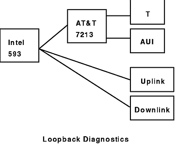
The LAN is diagnosed using a variety of loopbacks. The Loopback Diagnostics figure displays the chips that the diag command tests:
The diag command verifies the Intel 593 chip, which controls the LAN. If this command runs correctly, the loopbacks proceed through the Intel 593 out to the other ports of the 7318. You should run the appropriate loop test for the kind of failure you are having. Thus, if the 10BaseT port doesn't work, run the diag -w command, using the 10BaseT wrap. If the AUI doesn't work, run the diag -w command, using the AUI wrap. If the 7318 is attached to the LAN, using the uplink/downlink cables, run the diag -u command.
Notes:
- The 10BaseT loop test is not very strong. If the diagnostic passes this test and there are still problems, you may want to try the ipxping command.
- Both the 10BaseT and AUI ports go through common logic (the AT&T 7213). If this part is defective, neither port may work.
- The interface must be set before using the diag -w command.
If a problem is suspected with the printer ports, there are two quick methods of resolution. If a printer is already attached to one of the ports, run the diag command on that port, using the default sliding pattern. In this case, set the size parameter to 80 so that the pattern fits on the page. This indicates whether the port is working.
For a more thorough test, attach a printer loopback cable to printer ports 1 and 2 and run the diag -m test. This test outputs data to the device side and receives it on the pair side, verifying both the data and the toggling of the control signals on the printer interface.
If the test fails, note the kind of error you are getting. If there is a write timeout, the device side is probably at fault. If there is a read timeout, the pair side is at fault. Switch the sense of the test to the other port, and retry the test.
COM tests should be performed when a terminal does not work. There is a variety of tests that can be run, each more extensive than the previous test.
To verify the Intel 8530 serial controller, run the diag command without external loop plugs. Experiment with several speeds. If the command runs and a terminal is attached to the port, rerun the command at the terminal speed with the line pattern to check whether data displays on the terminal. If no data displays, the drivers may be defective or the terminal may be incorrectly cabled.
Use a single port wrap plug to check the drivers and receivers. Insert this plug in the port to be tested, and run the diag -w command.
Use loop cables, if you have problems with modem signals. Connect a loop cable from the suspected port to another port, and run the diag -m command. Pairs of ports (such as 0 and 1, or 2 and 3) use the same controller. This test is most effective if ports on different controllers are chosen.
The show command can display diagnostic values configurable by the set command. To display a diagnostic value, type:
show Item
where the Item parameter can be:
The show command displays values based on the last respective set command.