The 7318 is a multiprotocol communications server providing serial and parallel connectivity to Ethernet networks. Highlights of the P10 and S20 model include:
The 7318 Model S20 package includes:
Refer to "7318 Feature Codes and Part Number Information" for feature codes and order numbers of 7318 accessories.
The 7318 must be attached to your network in one of three ways:
The front panel of the 7318 provides 16 easily accessible serial ports. All 16 ports can operate simultaneously at data rates up to 115.2 Kbps. The serial ports support RS-232, RS-423, and RS-422 devices. RS-423 and RS-422 devices allow greater cabling distances (up to 2300 feet at 9600 baud). The 7318 is also RS-422 interoperable with restrictions. Refer to "Wiring and Interconnection".
The 7318 provides two parallel ports for network printing. These ports use standard DB-25 connectors, making it possible to attach most industry-standard printers to your network.
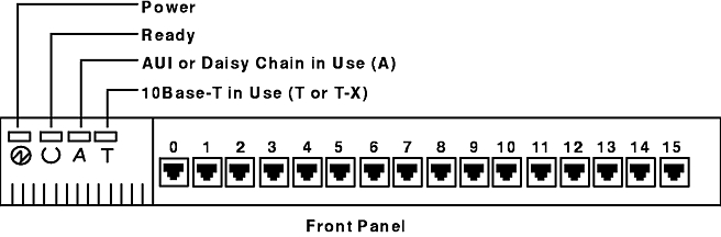
The front panel of the 7318 contains four indicator lights to show the status of the 7318 and 16 serial ports for interfacing with serial devices. The Front Panel figure illustrates the layout of the front panel.
The front panel components and their functions are:
| Serial ports | Connect RS-232, RS-422, or RS-423 serial devices to the 7318. These 16 RS-423 serial ports are numbered from left to right, 0 to 15, and are described more fully in "Connector Pinouts". |
| Status lights | Show the status of the 7318. From left to right, the lights correspond to Power, Ready, AUI or Daisy Chain in Use (A), 10Base-T in Use (T).
Refer to "Powering Up the 7318" for additional information about the four status lights. |
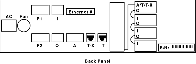
The back panel contains the AC socket, fan, parallel ports, Ethernet AUI port, daisy-chain port, and 10Base-T ports. The Back Panel figure illustrates the layout of the back panel.
The back panel components and their functions are:
| Universal AC Socket (IEC-320) | Provides the connection point for the power cord supplied with the 7318. |
| Fan | Provides ventilation to the internal components of the 7318. When installing your 7318, do not block the fan or the front vents. |
| Parallel ports | Connect parallel printers. These two industry-standard parallel ports, P1 and P2, are compatible with those on a PC. For pinout information, refer to "Connector Pinouts". |
| Daisy-Chain ports | Connect one 7318 to another. These two ports, I and O, allow connection of up to four 7318s, using a single Ethernet transceiver or 10Base-T connection. |
| Ethernet number | Specifies the 7318's Ethernet hardware address. This address applies to all of the Ethernet ports. Administrators should make a note of this address because they will need to refer to it during the installation process. |
| Ethernet AUI port | Connects to an Ethernet transceiver. Use this port and/or one of the 10Base-T ports to connect the 7318 to a network. For pinout information, refer to "Connector Pinouts". |
| 10Base-T ports | Specify two 10Base-T RJ-45 ports. Both ports (labeled T-X and T) connect to the same interface, but the wiring for each port is different. The T-X port is wired as a hub connection, allowing for direct connection to a host. The T port is wired as a client connection. Use either of these ports or the AUI port to connect the 7318 to a network. For pinout information, refer to "Connector Pinouts". |
| Daisy-Chain diagram | Illustrates the correct configuration for daisy-chaining four 7318s to a host system. |
| Serial number | Specifies the 7318's serial number. |
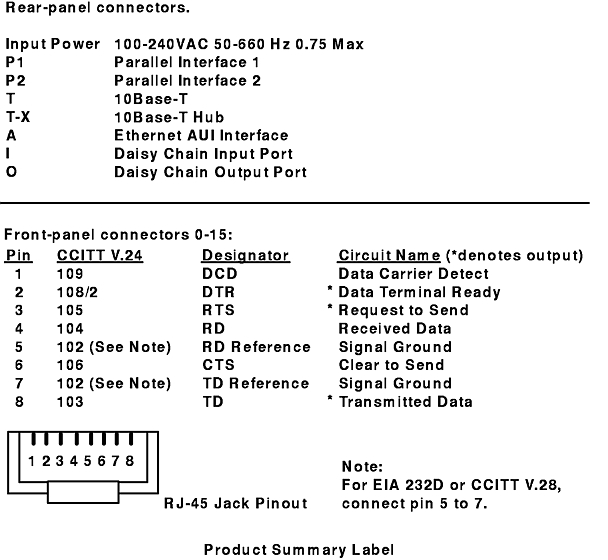
There is a product summary label affixed to the base panel on the bottom of the 7318. The Product Summary Label figure illustrates the information contained in the product summary.
Additional details on the connector and cable pinouts can be found in "Connector Pinouts".
The following figures depict five different configurations, each illustrating some aspect of 7318 connectivity.
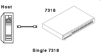
The Single 7318 figure depicts a direct-connect 7318. In this case, the RJ45 Ethernet cable would attach to the T-X port on the back of the 7318 and to the 10Base-T Ethernet port on the host. This is the simplest configuration and does not require an Ethernet transceiver or an Ethernet hub. However, no other devices can share the Ethernet in this configuration.
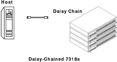
The Daisy-Chained 7318s figure depicts a direct-connect stack of 7318s daisy-chained to each other using the I and O ports. In this case, the RJ45 Ethernet cable would attach to the T-X port on the back of the first (top) 7318 and to the 10Base-T Ethernet port on the host. This configuration is like the configuration shown in the Single 7318 figure, except that up to 64 asynchronous ports can be attached on a single Ethernet connection. Each 7318 still maintains its own Ethernet address and acts independently. No other device types can share the Ethernet in this configuration.
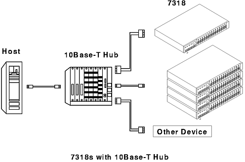
The 7318s with 10Base-T Hub figure depicts a single 7318 and four daisy-chained 7318s connected to a 10Base-T hub. In this case, the RJ45 Ethernet cable attaches to the T port on the back of the single 7318 and on the first (top) daisy-chained 7318. Using a 10Base-T hub allows the full flexibility of Ethernet 10Base-T wiring.
Note: The four daisy-chained units are addressed and act as if they are four separately connected units.
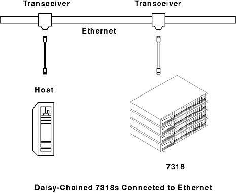
The Daisy-Chained 7318s Connected to Ethernet figure depicts four daisy-chained 7318s connected to an Ethernet network. In this case, the cable connects to the AUI port or the T port on the back of the 7318. Only one transceiver is necessary when 7318s are daisy-chained. With 10Base-2 or 10Base-5 Ethernet, longer distances can be used. Again, this arrangement allows for full flexibility in network layout and implementation.
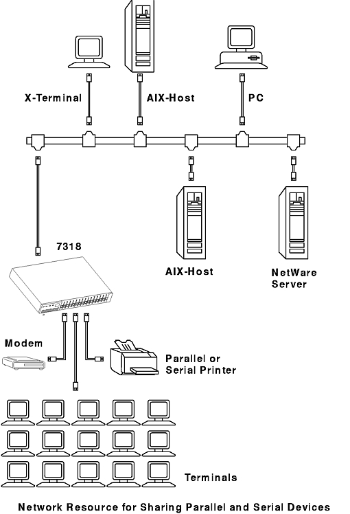
The Network Resource for Sharing Parallel and Serial Devices figure depicts a 10Base-2 or 10Base-5 network with several systems and devices attached to the Ethernet. The devices attached to the 7318 are resources available to the network and are configured and used by the various network hosts.