This appendix contains pinout information for the following ports:
This appendix also contains cable pinout information for the following:
This interface conforms to the electrical specifications of EIA RS-423A and has a minimum driven voltage swing of +5.6V to -5.6V in a 3K load to ground. The interface is wired as a data terminal equipment (DTE) driving TXD and receiving RXD. The interface is the same on all 16 serial ports of the concentrator. The following tables show the configuration of the interface:
| Normal Mode Pinout | |||
| Pin | Designator | Circuit Name | CCITT Number |
| 1 | DCD | Received Line Signal Detector | 109 |
| 2 | DTR | DTE Ready | 108/2 |
| 3 | RTS | Request to Send | 105/133 |
| 4 | RD | Received Data | 104A |
| 5 | RD REF | DCE Common Return | 102b/104B |
| 6 | CTS | Clear to Send | 106 |
| 7 | TD REF | Signal Ground | 102 |
| 8 | TD | Transmitted Data | 103 |
Note: The input circuits are biased for fail-safe operation so that if no connection is attached, the circuits will read as follows:
| Disconnected State | |||
| Pin | Designator | Circuit Name | Disconnect State |
| 1 | DCD | Received Line Signal Detector | False |
| 4 | RD | Received Data | Break |
| 6 | CTS | Clear to Send | False |
TD REF provides a common ground reference for TXD+, DTR, and RTS. It is connected to the system ground. RD REF provides a common reference for RXD+, DCD, and CTS but is isolated with respect to the system ground.
The following information describes the necessary wiring for cables that connect between the 7318 and various serial hardware devices.
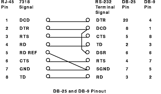
The DB-25 or DB-9 Pinout figure depicts an expanded null modem that translates the appropriate control signals for connecting a terminal to the 7318. It also shows how the terminal signals relate to pins on the DB-25 and DB-9 connectors.
Order the DB-25 terminal adapter as Feature Code 7904 and the DB-9 terminal adapter as Feature Code 7905.
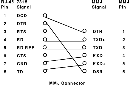
Recent Digital Equipment Corporation (DEC) terminals (and clones) use a connector that DEC calls a modified modular jack (MMJ) connector. To attach a terminal with this type of connector, you need a special adapter. The MMJ Connector figure depicts the MMJ circuits and pins.
Order the RJ45 to MMJ cable as Feature Code 7907.
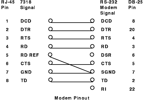
The Modem Pinout figure maps the control signal between an RS-232 modem and the 7318 to preserve modem control functions. The figure also depicts how the modem signals relate to pins on a DB-25 connector.
Order the DB-25 modem adapter as Feature Code 7903.
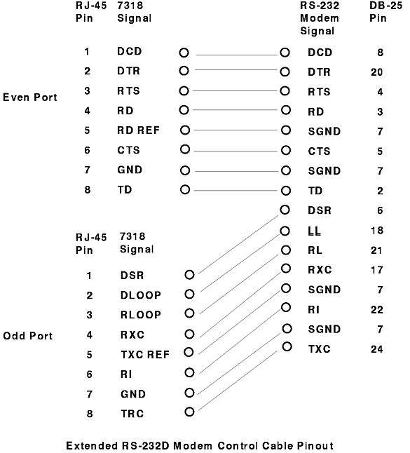
The Extended RS-232D Modem Control Cable Pinout figure includes the DSR and RI signals. Order the Extended RS-232D Modem Control Cable as Feature Code 7902.
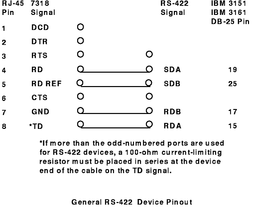
The general RS-422 Device Pinout figure depicts the pinout for cabling an RS-422 device and the 7318. This figure is also applicable to the 7318 Model P10 when configuring a TTY device and not an LP or printer device. This figure is also applicable to the 7318 Model S20 ports, not configured as P10-style ports, with any RS-422 device type.
The figure below is applicable to 7318 P10-style ports that are connected to RS-422 printers and are configured as native LP devices. You will notice that this configuration required additional wiring to connect RTS to CTS and DTR to DCD. These jumpers are required by AIX for serial printers and can be made at either end of the cable.
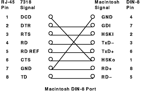
The Macintosh DIN-8 Port figure depicts the pinout for cabling a 7318 to Macintosh computers with DIN-8 style communications ports.
Order the Macintosh DIN 8 cable as Feature Code 7906.
The 7318 has a standard DB-25F parallel interface.
| Parallel Port Pinout | ||
| Pin | Signal | Direction |
| 1 | -Strobe | Out |
| 2-9 | Data | Out |
| 10 | -Ack 1 | In |
| 11 | Busy | In |
| 12 | PE | In |
| 13 | Slct | In |
| 14 | -Autofd | Out |
| 15 | -Error | In |
| 16 | -Init | Out |
| 17 | -Slct in | Out |
| 18-25 | Ground | |
The following two tables describe the 10Base-T pinouts:
The T port uses four of the eight available pins to connect to a 10Base-T hub, as shown in the following table:
| T Port Pinout | |
| Connector Pin | Signal Name |
| 1 | TD+ |
| 2 | TD- |
| 3 | RD+ |
| 4 | |
| 5 | |
| 6 | RD- |
| 7 | |
| 8 | |
The T-X port also uses four of the eight possible pins but crosses the RD and TD pins to directly connect to a host instead of a 10Base-T hub, as shown in the following table:
| T-X Port Pinout | |
| Connector Pin | Signal Name |
| 1 | RD+ |
| 2 | RD- |
| 3 | TD+ |
| 4 | |
| 5 | |
| 6 | TD- |
| 7 | |
| 8 | |
The following table describes the adapter unit interface (AUI) port pinout:
| AUI Port Pinout | ||
| Pin | Circuit | Use |
| 3 | DO-A | Data Out circuit A |
| 10 | DO-B | Data Out circuit B |
| 11 | DO-S | Data Out circuit shield |
| 5 | DI-A | Data In circuit A |
| 12 | DI-B | Data In circuit B |
| 4 | DI-S | Data In circuit shield |
| 7 | Unused | |
| 15 | Unused | |
| 8 | Unused | |
| 2 | CI-A | Control In circuit A |
| 9 | CI-B | Control In circuit B |
| 1 | CI-S | Control In circuit shield |
| 6 | Vc | Voltage Common |
| 13 | VP | Voltage Plus |
| 14 | VS | Voltage Shield |
| Shell | PG | Protective Ground |