To install the 7318 hardware, follow these four basic steps:
The 7318 can adapt to many environments. You can place the unit on a desktop, mount it on a wall, or mount it in a standard 19-inch EIA rack. The information in the following sections describes these steps in more detail.
The 7318 can be positioned on any surface provided you do not block the air flow from the front and rear of the unit.
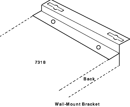
Wall mounting works well for a single 7318. When mounting multiple 7318s, install a shelf on the wall and place the 7318s on the shelf or use an EIA rack.
Use rack mounting to install one or more 7318s in a single location. Mount the 7318 in the rack, using the optional rack-mounting brackets, or place the 7318s on a standard rack shelf.
To mount the 7318 in an EIA rack:
The following information briefly describes the choices for attaching to a network. You can choose between attaching the 7318 to a host adapter, a hub, or an external Ethernet transceiver. For more information, refer to "Ethernet Overview". The following cables are available for network attachment:
The AUI port connects the 7318 to an external transceiver (Part Number 02G7437 (Thin) or Part Number 02G7431 (10Base-T)) for the Ethernet network. You can use AUI or 10Base-T but only one can be active at a time (unless in a high-availability (HA) environment). The AUI port supports a directly attached transceiver or a cable to a remote transceiver. AUI transceiver cables are specially designed for this application and normally come with the transceiver. Refer to "Ethernet Overview" for more information.
If you are in an HA environment, attach cables to both the AUI and T ports, one to each Ethernet network.
Note: Only one Ethernet network is used at a time.
You can use standard 10Base-T unshielded twisted-pair (UTP) cable to connect to a 10Base-T hub. There are no performance advantages to using a particular Ethernet port on the 7318. When attaching to a 10Base-T hub, connect the cable from the hub to the T port on the 7318. Use the T port as the second Ethernet connection in an HA environment.
You can use standard 10Base-T unshielded twisted-pair (UTP) cable to connect to a 10Base-T host adapter. There are no performance advantages to using a particular Ethernet port on the 7318.
When attaching directly to a 10Base-T host adapter, connect the cable from the host adapter to the T-X port on the 7318. The following procedure explains this simple installation process. In this instance, other network hosts share the 7318 only through the attached host.
To install a 7318 directly to a host:
Note: If you need a longer cable than the 10 foot RJ-45 to RJ-45 cable (Feature Code 7901), be sure to use a cable designed for 10Base-T. Refer to "Twisted Pair Cable" for more information on the appropriate type of cable to use.
If you are planning to connect more than one 7318 to the network, you can either connect the 7318s individually or use daisy-chain connectors. Using the daisy-chaining feature reduces the number of hub or host adapter connectors required for the additional 7318s.
The P10 and S20 Models can be mixed in a single daisy-chain.
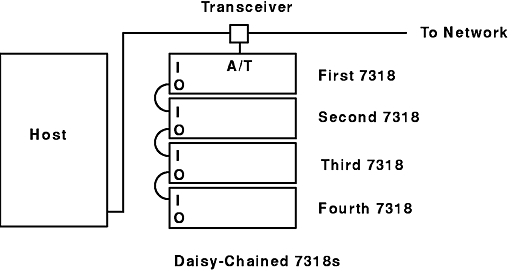
Using the 7318 I (In) and O (Out) ports and daisy-chain cable, you can attach up to four 7318s to the same Ethernet connection. This reduces the need for separate transceivers and additional 10Base-T hub ports. Daisy-chained 7318s each maintain their own Ethernet and IP addresses, load, and operate independently.
Use the daisy-chain cable (Feature Code 7909) to connect one 7318 to another. You must remove power to all 7318s in the daisy-chain group before installing a daisy-chain cable. If you plug in a daisy-chain cable to an operating unit, the Ethernet interface will not operate properly. You must power cycle the unit, because the 7318s recognize their daisy-chain configuration only when they power up.
The 7318 that is attached to the Ethernet is called the "first" in the chain. Only the first 7318 is connected to the Ethernet; the rest are connected through the daisy-chain connectors.
The additional 7318s are attached in order; that is, the second is attached to the first, the third to the second, and the fourth to the third. The last 7318 in the line is connected to only one other. Use the O (Out) connector of the higher 7318 to connect to the I (In) connector of the lower 7318.
The Daisy-Chained 7318s figure illustrates the cabling relationship among four daisy-chained 7318s as well as their relationship to the host.
While the daisy-chain feature is easy to use, you must observe a few rules when chaining 7318s:
The 7318 does not provide a power on/off switch. You must use the AC plug to power on and power off the 7318.
Plug in the 7318 to ensure that the server is functional. The lights on the front will turn on or stay off in different configurations depending on the state of the 7318, the download, and the network.
The operation of these lights is as follows:
Note: Ethernet transceivers must support SQE heartbeat for the AUI light to function properly. If your transceiver does not support SQE heartbeat, the AUI light will not light.
Note: Daisy-chained 7318s only display the AUI port light, even if the first 7318 is connected using the 10Base-T (T or T-X) port.
You can now attach the cables for terminals, printers, and modems to your 7318. "Wiring Serial Devices" describes serial devices such as terminals, modems, and serial printers. "Connector Pinouts" describes the pinouts for all cables. The following cables are available for attaching devices:
Each cable measures 10 feet in length.
Use the planning chart to assist you in planning your cable configuration. There is a blank chart for your use following the example.