DMA Controller
DMA
Controller Architecture (Jul 1992) (98 pages)Type 1 and 2 Controllers with their features and programming.
The original 1990-section covers only the base (Type 1) DMA controller.
There are a number of patents out there.
DMA Controller Architecture pg 7-14
PIO Interface pg 15-38
SCB Interface pg 39-82
Appendices A: Architecture Compliance, B. FIFO [App A, pg 83, App B pgs 85-93]
DMA Controller Architecture
DMA Controller Organization
System Interfaces
States
Idle State
Program State
Transfer State
DMA Controller Resets
Programming Considerations
DMA Controller Architecture
The direct-memory-access (DMA) controller is a system component that has the single task of managing the transfer of data between two addressable locations within the system address space. Using the DMA controller to manage data transfers relieves the system master of having to perform these transfers.
The DMA controller consist of eight channels. Each channel can be programmed to perform specific operations using specific parameters. Each channel can be set to respond to a specific arbitration level.
The DMA operations supported by each channel include data-transfer operations and the memory-verify operation. Data-transfer operations move data between an I/O device and memory. Memory-verify operation performs a memory read cycle but does not perform a write cycle or transfer any data.
The DMA controller architecture provides two interfaces to control DMA operations: programmed-l/O (PIO) and subsystem control block (SCB). The PIO interface supports a 24-bit memory address and an 8- or 16-bit data width through a set of registers and I/O ports. The SCB interface supports a 32-bit memory address and an 8-, 16-, or 32-bit data width through a control-block interface.
The DMA controller for all systems based on the Micro Channel architecture must support the PIO interface. In addition, the Type 2 DMA controller provides the SCB interface.
DMA Controller Organization
The architecture for the DMA controller consists of two interfaces; each interface provides its own method of performing DMA operations.
PIO interface, which uses a set of I/O registers to control the DMA operations
SCB interface, which uses control blocks to control DMA operations
The relationship of the functional interfaces that support these architectures is shown in the following figure.
Figure 1. Structure of DMA Architecture
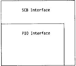
Figure 2. Register Comparison — PIO to SCB Interfaces
I/O-Memory Address;8;16;R/W;32;R
Memory Address;8;24;R/W;32;R
Transfer Count;8;16;R/W;32;R
DMA Mode;8;8;R/W;16;R
DMA Mask;8;8;W;8;R
Arbitration Level;8;8;R/W;8;R/W
DMA Status;1;16;R;16;R
Function;1;8;W;8;R/W
Extended Function;1;-;-;8;R/W
Control Block Address;8;-;-;32;R/W
Attention;1;-;-;8;W
Subsystem Control;1;-;-;8;R
Command Busy/Status;1;-;-;8;W
Indirect List Address;8;-;-;32;R
Indirect List Count;8;-;-;32;R
System Interfaces
The I/O addresses assigned to the DMA controller are not accessible through the channel. These registers can be directly accessed only through I/O read and write operations from the system master.
Figure 3. DMA Controller I/O Addresses Assignment
I/O Address (hex);Description
0000-000F;AT-compatible interface
0010-001F;PIO and SCB interfaces
0081-00SF;AT-compatible interface
00C0-C0DF;AT-compatible interface
Figure 4. PIO and DMA Controller I/O Addresses Assignment
I/O Address;Description;PIO;SCB
0010-0017;Reserved;;
0018;Function register;WO;R/W
0019;Extended Function register;-;R/W
001A;Execute Function port;R/W;R/W
001B;Reserved;;
001C;Attention register;-;WO
0010;Subsystem Control register;-;WO
00TE;Reserved;;
001F;Command Busy/Status register;-;RO
States
The DMA controller operates on the registers and data based on its current state.
The DMA controller has three states:
Idle state
Program state
Transfer state
The controller, acting on behalf of different DMA channels, cannot be in more than one state at a time. In each state, the DMA controller monitors various conditions to determine the next operation to perform and what state to enter next.
Idle State
The idle state is the default state for the DMA controller. The DMA controller enters this state after it is reset or after exiting from one of the other two states. While in the idle state, the DMA controller monitors the address bus and control signals to determine if an I/O cycle is occurring and monitors the arbitration bus and ARB/-GNT to determine if an arbitration cycle is occurring.
If an I/O cycle selects a DMA controller register, the DMA controller enters the program state and prepares to process the command. During an arbitration cycle, the DMA controller monitors the arbitration bus. It enters the transfer state if the system channel is granted to an arbitration level that matches a value in an Arbitration Level register and the DMA channel ts enabled. When the DMA controller enters the idle state after a system reset, its registers are initialized to a default state. (For information on the default state for these register, see “DMA Controller Resets” on page 7.)
Program State
The DMA controller enters the program state whenever it detects an I/O cycle with an address within the address range assigned to the DMA controller.
The DMA controller is in the program state whenever commands are being issued that modify or return the contents of its registers. These commands are defined by the interfaces for PIO and SCB architectures.
The DMA controller exits from the program state after each I/O cycle is completed and returns to the appropriate state, either the idle state or the transfer state.
Transfer State
The DMA controller is in the transfer state whenever it is driving the control signals and the address bus. It drives these signals while performing a DMA transfer operation (data transfer or memory-verify) or an SCB fetch operation (a control block or an indirect list).
The DMA controller enters the transfer state from the idle state when all of the following conditions exist:
An arbitrating device has been granted control of the system channel.
The arbitration level matches the value in one of the Arbitration Level registers.
The DMA channel with the matching arbitration level is enabled.
If more than one DMA channel meets these conditions, the lower-numbered DMA channel gets control and starts its DMA operation. After the lower-numbered channel has completed its operation, the next channel gets control and starts its operation. This continues until all operations for that arbitration level are completed.
NOTE: Although the DMA controller supports assigning the same level to more than one channel, IBM recommends that each DMA channel be assigned a unique arbitration level.
The DMA controller exits from the transfer state and returns to the idle state after an end-of-transfer is signaled or if a DMA error is detected. The end-of-transfer is signaled:
After the DMA controller completes a single transfer for a nonbursting device
After the DMA controller reaches the terminal count
After a bursting device stops driving the ‘burst’ signal and the DMA controller has completed the current transfer
DMA Controller Resets
The DMA controller controller can perform up to four levels of reset. The local bus is held not-ready until the reset operation has been completed.
Hardware reset
Is performed when the system is first powered-on. This level of reset initializes all the registers, functions, and state machines in the DMA controller to a known state.
Controller reset
Is performed by issuing the DMA Controller Reset command. This reset is similar to the hardware reset except that it initializes only the DMA controller registers and functions. It leaves system functions, such as arbitration and refresh, intact.
Channel reset
is performed by issuing the DMA Channel Reset command. This command allows the programmer to reset a specific DMA channel without interfering with the other DMA channels. This reset affects only the registers, fields, and logic that pertain to the DMA channel being reset. For registers containing fields for more than one DMA channel, only the fields for the specified channel are reset. All DMA logic used during an active DMA transfer, including the state machine are also reset. The channel reset is only supported by the SCB interface.
Bus timeout reset
is performed when a DMA channel has gained control of the system channel and a bus timeout occurs. This reset is similar to a channel reset except that DMA Status register is not reset.
DMA registers and content after DMA hardware reset (H), controller reset (S), channel reset (C), or bus timeout reset (T).
Figure 5. DMA Register Reset Initialization
Register;Reset Type;State After Reset
Function;;Not initialized
Extended Function;;Not initialized
Byte Pointer;H,S,C;Points to low byte
DMA Status;H,S,C;All status is cleared
Arbitration Level;H;Each channel is set to its channel number (see Figure 6)
DMA Mask;H,S,C,T;Channels disabled (hex FF)
DMA Mode;;Not initialized
l/O-Memory Address;;Not initialized
Memory Address;;Not initialized
Transfer Count Not initialized
Command Busy/Status;H,S,C;No errors and Attention register not busy
Attention;H,S,C;No active requests
Control Block Address;;Not initialized
Indirect List Address;;Not initialized
Indirect List Count;;Not initialized
FIFO Byte Count;H,S,C,T;FIFO empty (hex 00)
The system initializes the Arbitration Level registers during a system or DMA controller reset to the following values.
Figure 6. Default Arbitration-Level Values
DMA Channel;Arbitration Level
Channel 0;0
Channel 1;1
Channel 2;2
Channel 3;3
Channel 4;4
Channel 5;5
Channel 6;6
Channel 7;7
Programming Considerations
For both PIO and SCB interfaces, use the following for proper DMA operation.
1. Disable interrupts when using any multiple-byte commands.
2. Initialize all DMA register values before enabling the I/O device.
For SCB operations, the control block must be set up in memory and the request enqueued before enabling the I/O device.