DMA Controller PIO
Interface
DMA
Controller Architecture
(Jul 1992) (pg 15-38)Type 1 and 2 Controllers with their features and programming.
The original 1990-section covers only the base (Type 1) DMA controller.
NOTE: Lots of images that IBM didn't label. I think I got 'em all. Maybe. -LFO
PIO Interface
In the programmed-I/O (PIO) interface, the system master uses a set of programmable registers to:
Specify the type of operation
Establish the addresses and direction
Specify the number of transfers for a given operation
Select the channel to be used
Each channel uses its own 24-bit memory address register and 16-bit transfer counter to define each DMA operation. Data width for each transfer can be set to 8 or 16 bits. Therefore, each channel can be set up to perform 64K transfers (up to 128KB) within a single, contiguous block of memory addresses from 0 to 16MB (224), independent of the setting of the other DMA channels.
Each channel is preset to respond to an arbitration level equal to its channel number. In addition, the arbitration levels for DMA channels 0 and 4 can be modified to respond to other values.
PIO Interface Registers
The PIO interface registers control and monitor the state of the DMA controller and each DMA channel in the DMA controller. The registers can be divided into three functional categories: system Interface, operational interface, and transfer control.
The following shows the registers and ports used, and the I/O addresses associated, with the PIO interface. The page number indicates where the register is described.
Figure 7. I/O Addresses and Registers - PIO Interface
I/O Address;R/W;Register;Page Number
System Interface Registers;;;
0018;Function;W;11
001A;Execute Function port;R/W;na
;Byte pointer;na;12
Operation Control Registers;;;
;Arbitration Level;R/W;13
;DMA Mask;W;14
;DMA Status;R;15
Transfer Control Registers;;;
;DMA Mode;R/W;16
;I/O-Memory Address;R/W;17
;Memory Address;R/W;18
;Transfer Count;R/W;18
;Data Holding;na;18
R/W;Read/Write;R;Read only
na;Not available;W;Write only
NOTE: Programs and hardware writing to reserved areas should ensure that the areas are set to 0 (unless otherwise indicated); programs and hardware reading these areas should treat reserved values as don’t care.
System interface Registers
These registers control the overall interface to the DMA controller and each of the DMA channels.
Function Register
The Function register is an 8-bit, write-only register that is used to select the DMA channel and specify the command to be performed. The Function register is loaded using the Write Function command (see page 25).

FUNC The Function field (bits 7-4) selects a command to be performed by the specified DMA channel. (For information on command selection, see “Commands” on page 24.)
SEL The Select field (bits 2—0} specifies the DMA channel that is to perform the PIO command.
Byte Pointer
The byte pointer is a 2-bit, internal register that is used to point to the individual bytes in multiple-byte registers. The byte pointer is increased by 1 for each read or write operation to the Execute Function port (hex 001A).
The contents of the byte pointer cannot be accessed. The byte pointer is cleared (set to point to the first byte of a register) automatically after a Write Function command (see page 25).

After the byte pointer is cleared, it points to bits 7—0 of a multiple-byte register. As each byte in the register is accessed, the byte pointer is increased to point to the next byte within the register. After the last byte (high byte) within the register is accessed, the byte pointer is undefined and must be cleared (set to point to the first byte).
Operation Control Registers
These registers are used to control the operation of and maintain the status for each DMA channel.
Arbitration Level Registers
There are eight Arbitration Level registers, one for each DMA channel. Each register is an 8-bit register that contains the arbitration level assigned to the specific DMA channel.
The registers for DMA channels 0 and 4 are read/write. The registers for the other
DMA channels are not accessible.
The registers are accessed using the Read or Write Arbitration Level command (see page 33).
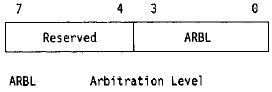
ARBL The Arbitration Level field (bits 3-0) specifies the arbitration level for the specific DMA channel.
DMA Mask Register
The DMA Mask register is an 8-bit, write-only register that contains one field for each DMA channel. The individual fields determine whether DMA operations are enabled or disabled for that channel. If DMA operations are enabled for a DMA channel, the DMA controller enters the transfer state when the system channel is granted to the arbitration level for that DMA channel.
The individual fields are set to 1 using the Set DMA Mask command, and set to 0 using the Reset DMA Mask commands (see page 25). All fields are set to 1 after performing a Reset DMA Controller command (see page 26).

M7 - M0 The Mask fields (bits 7 —0) are used to enable and disable DMA operations on each of the DMA channels. When a Mask field is set to 1, the mask is set and the channel is disabled. When a Mask field is set to 0, the mask is reset
and the channel! is enabled. The Mask field is set to 1 by the DMA controller after the DMA channel has completed or terminated a DMA transfer operation.
DMA Status Register
The DMA Status register is a 16-bit, read-only register that contains the status for the eight DMA channels. As each byte is read, its status is cleared (the byte is set to 00). Performing a Reset DMA Controller command clears the status in both bytes.
The DMA Status register can be read using the Read DMA Status command (see page 30).
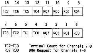
TC7-0 The Terminal Count fields (bits 15—12 and 7 — 4) indicate whether the corresponding DMA channel has completed a DMA operation (transfer count has passed 0) since the status was previously cleared. If the field is 1, the channel has completed a DMA operation; if the field is 0, the channel has not completed a DMA operation.
RQ7-0 The DMA Request fields (bits 11—8 and 3—0) indicate whether the corresponding DMA channel has transferred data since the status was previously cleared. If the field is 1, the channel has been active; if the field is 0, the channel has not been active.
Transfer Control Registers
These registers determine the operation of the DMA channel and are used to control the source and destination addresses of each transfer and the number bytes transferred.
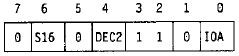
DMA Mode Registers
There are eight DMA Mode registers, one register for each DMA channel. Each register is an 8-bit, read/write register that controls the operation of that DMA channel.
The register is accessed using the Read or Write DMA Mode command (see page 30).
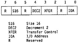
S16 The Size 16 field (bit 6) specifies the minimum data width used during the I/O cycle and determines whether the transfer count is the number of bytes or words to be transferred. When the field is set to 1, the transfer count represents the number of words to transfer. When the field is set to 0, the transfer count represents the number of bytes to transfer.
When a 16-bit transfer is performed to an I/O device, the I/O address is aligned on a word boundary (address bit 0 is 0), regardless of the address in the I/O-Memory Address register.
DEC2 The Decrement 2 field (bit 4) specifies whether the DMA controller increases or decreases the address in the Memory Address register. When the field is set to 1, the Memory Address register is decreased by 1 for each byte transferred. When the field is set to 0, the Memory Address register is increased.
XFER The Transfer Control field (bits 3 and 2) specifies the type of operation to be performed by the DMA channel.
Figure 8. DMA Operation Selection
Transfer Control;Operation Performed
0 0;Memory verify
0 1;Memory-to-I/O transfer (memory is the source)
1 0;Memory verify
1 1;I/O-to-memory transfer (memory is the destination)
IOA The I/O Address field (bit 0) specifies whether to use the I/O address in the |/O-Memory Address register or to use I/O address hex 0000. When the field is 1, the DMA controller uses the address in the I/O-Memory Address register for the DMA operation. When the field is 0, the DMA controller uses I/O address hex 0000 for the DMA transfer.
I/O-Memory Address Registers
There are eight I/O-Memory Address registers, one for each DMA channel. Each register is a 16-bit, read/write register that contains the I/O address used during the DMA transfers for that DMA channel.
The l/O-Memory Address register is accessed using the Read or Write I/O Address command (see page 27).

Memory Address Registers
There are eight Memory Address registers, one for each DMA channel. Each register is a 24-bit, read/write register that contains the memory address used during a DMA transfer. The memory address is increased or decreased as data is transferred.
The register is read using the Read Memory Address command (see page 28) and is loaded using the Write Memory Address command (see page 28).
Transfer Count Registers
There are eight Transfer Count registers, one for each DMA channel. Each register is a 16-bit, read/write register that contains the number of transfer cycles to be performed. The register is decreased by the appropriate amount for each transfer cycle.
The Transfer Count register is read using the Read Transfer Count command (see page 29) and is loaded using the Write Transfer Count command (see page 29).
Data Holding Register
The DMA controller uses the Data Holding register to temporarily store the data being transferred. The minimum size of the Data Holding register is 2 bytes and the maximum is 255 bytes.
Data Structures
The DMA controller defines two transfer-control structures used by the PIO interface, which define the physical limits of the transfer.
Address
The memory addressing is limited to 24 bits. Memory addresses that are increased beyond hex 0FFFFFF or decreased below 00 are undefined and cause compatibility problems in systems with 32-bit addressing.
When decreasing the memory address, the starting memory address must be aligned on a word boundary for DMA transfers using 16-bit data widths.
The I/O address can be aligned on a byte or word boundary. However, the DMA controller forces the I/O address to align on a word boundary when the width is specified as 16-bits.
Transfer Count
The transfer count is a 16-bit, zero-base value; a transfer count of hex 00 results in one transfer cycle.
Operations
The DMA operation to be performed is determined by the values loaded into the DMA Mode register, and determines how certain registers are used. The following describes how each of the registers is used for each type of operation.
All Operations
The following registers have the same usage for all DMA operations.
Arbitration Level Register: This register is used to associate an arbitration level to a DMA channel. If the DMA channel is enabled, the DMA controller starts a DMA operation when the corresponding arbitration level is granted control of the system channel. If more than one DMA channel has the same arbitration level, the operations are performed for all channels, starting with the lowest DMA channel.
If the winning arbitration level matches the level specified for a DMA channel that is disabled, the DMA controller remains in the idle state. (A bus timeout will occur if another master does not take control of the system channel.)
DMA Mask Register: The appropriate Mask field must be set to 0 (enabled) for the DMA transfer operation to begin. The DMA controller sets the field to 1 (disabled) after it completes the DMA operation.
DMA Status Register: The DMA Status register indicates whether or not a DMA channel was active and whether or not a DMA operation has been completed.
The DMA controller sets a DMA Request field to 1 every time the DMA channel starts an operation. It sets the Terminal Count field to 1 after the terminal count changes from 0000 to hex FFFF to indicate that the DMA channel has completed an operation.
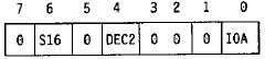
Memory-Verify Operation
During the memory-verify operation, the DMA controller performs a memory-read cycle, but does not perform an I/O- or memory-write cycle. The operation begins when the arbitrating device is granted control of the system channel, if the DMA channel is enabled.
NOTE: All registers must be loaded with the appropriate values before starting the DMA operation.
DMA Mode Register: For memory-verify operations, the DMA Mode register is set to the following. The Size 16, Decrement 2, and I/O Address fields are set to the appropriate values, depending on the options desired.
I/O-Memory Address Register: This register is not used.
Memory Address Register: The Memory Address register points to the next memory location and is increased or decreased the appropriate amount, depending on the setting of the Decrement 2 field and the width of the transfer.
Transfer Count Register: The Transfer Count register contains the number of bytes or words that remain to be transferred (the Size 16 field determines whether the count value represents bytes or words). The count value is decreased the appropriate amount after the memory-read cycle. The DMA operation is completed (TC is driven active) when the transfer count goes from 0000 to hex FFFF.
Memory-to-I/O Transfer Operation
The memory-to-I/O transfer operation reads data from a location in memory and writes the data to an I/O device. The operation begins when the arbitrating device is granted control of the system channel, if the DMA channel is enabled.
NOTE: All registers must be loaded with the appropriate values before starting the DMA operation.
DMA Mode Register: For memory-to-I/O transfer operations, the DMA Mode register is set to the following. The Size 16, Decrement 2, and I/O Address fields are set to the appropriate values, depending on the options desired.
I/O-Memory Address Register: lf the I/O Address field is set to 1, the DMA controller drives the address specified in this register onto the address bus during the I/O-write cycle. If the I/O Address field is set to 0, this register is not used, and the DMA controller drives address hex 0000 onto the address bus.
If the Size 16 field is set to 1, the DMA controller forces the I/O address to a word boundary (address bit 0 is driven to 0) and writes at least one word to the I/O address before performing another memory-read cycle or ending the transfer.
The I/O address remains unchanged during DMA operations.
Memory Address Register: The Memory Address register points to the next memory location and is increased or decreased the appropriate amount, depending on the setting of the Decrement 2 field and the width of the transfer.
Transfer Count Register: The Transfer Count register contains the number of bytes or words that remain to be transferred (the Size 16 field determines whether the count value represents bytes or words). The count value is decreased the appropriate amount after the I/O-write cycle. The DMA operation is completed (TC is driven active) when the transfer count goes from 0000 to hex FFFF.
I/O-to-Memory Transfer Operation
The I/O-to-memory transfer operation reads data from an I/O device and writes the data to a location in memory. The operation begins when the arbitrating device is granted control of the system channel, if the DMA channel is enabled.
NOTE: All registers must be loaded with the appropriate values before starting the DMA operation.
DMA Mode Register: For |/O-to-memory transfer operations, the DMA Mode register is set to the following. The Size 16, Decrement 2, and I/O Address fields are set to the appropriate values, depending on the options desired.
I/O-Memory Address Register: lf the I/O Address field is set to 1, the DMA controller drives the address specified in this register onto the address bus during the I/O-read cycle. If the I/O Address field is set to 0, this register is not used, and the DMA controller drives address hex 0000 onto the address bus.
lf the Size 16 field is set to 1, the DMA controller forces the I/O address to a word boundary (address bit 0 is driven to 0) and reads at least one word from the I/O address before performing the memory-write cycle.
The !/O address remains unchanged during DMA operations.
Memory Address Register: The Memory Address register points to the next memory location and is increased or decreased the appropriate amount, depending on the setting of the Decrement 2 field and the width of the transfer.
Transfer Count Register: The Transfer Count register contains the number of bytes or words that remain to be transferred (the Size 16 field determines whether the count value represents bytes or words). The count value is decreased the appropriate amount after the memory-write cycle. The DMA operation is completed (TC Is driven active) when the transfer count goes from 0000 to hex FFFF.
Commands
These commands modify the state of the DMA controller, set parameters for other commands or DMA operations, or return information on the state of the DMA controller. There are two categories of commands through the Function register:
* Immediate commands
* Execute commands
All commands consist of an I/O write operation to the Function register (at address hex 0018). The immediate commands are those functions selected through the Function register that directly cause the DMA channel or DMA controller to perform some operation. The execute commands are those functions selected through the Function register that are performed when the Execute Function port (at hex 001A) is accessed.
The following shows the relationship between the functions selected and the command category.
Figure 9. PIO Commands
Function (hex);Command;Category
00;Read or write I/O address;Execute
01;Reserved;
02;Write memory address;Execute
03;Read memory address;Execute
04;Write transfer count;Execute
05;Read transfer count;Execute
06;Read DMA status;Execute
07;Read or write DMA mode;Execute
08;Read or write arbitration level;Execute
09;Set DMA mask;Immediate
0A;Reset DMA mask;Immediate
0B, 0C;Reserved;
0D;Reset DMA controller;Immediate
OE, OF;Reserved;
Function Register Commands
The PIO interface supports only one function-register command.
Write Function
This command loads the transferred data byte into the Function register. The Function field specifies the command to be performed and the Select field specifies the DMA channel.
This command sets the byte pointer to binary 00.

Immediate Commands
For the immediate commands, writing to the Function register causes the operation to be performed. The Select field specifies the DMA channel. These commands are performed immediately and do not require additional I/O accesses to the Execute Function register. The immediate commands are:
* Set DMA Mask
* Reset DMA Mask
* Reset DMA Controller
Set DMA Mask
This command sets the Mask field to 1 for the specified DMA channel. Setting the Mask field to 1 disables the DMA channel. The DMA channel is specified in the Select field.
Reset DMA Mask
This command sets the Mask field to 0 for the specified DMA channel. Setting this field to 0 enables the DMA channel. The DMA channel is specified in the Select field.

Reset DMA Controller
When it receives this command, the DMA controller:
* Terminates all transfer operations for all DMA channels
* Sets the byte pointer to binary 00
* Sets all mask fields to 1 to disable the DMA channels
* Sets all fields in the DMA Status register to 0
The Select field does not affect this command and should be set to 0.
Execute Commands
These commands are issued in two parts. First, the Function register is loaded with the appropriate values. Then, the Execute Function port (hex 001A) is accessed to complete the command. The number of accesses is determined by the number of bytes in the register.
When multiple-byte registers are being accessed, the byte pointer determines which byte in the register is accessed. The Write Function command resets the byte pointer to point to byte 0 (bits 7-0).
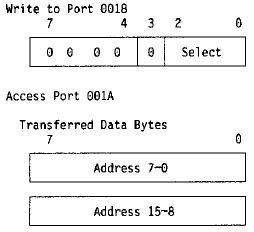
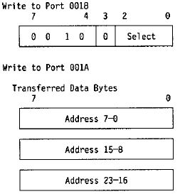
Read or Write I/O Address
The read command returns the contents of the I/O-Memory Address register in byte increments. The write command loads the transferred data byte into the appropriate byte of the I/O-Memory Address register.
The DMA channel is specified in the Select field.
Write Memory Address
This command loads each transferred data byte into the appropriate byte of the Memory Address register.
The DMA channel is specified in the Select field.
Read Memory Address
This command returns the content of the Memory Address register in byte increments. The DMA channel is specified in the Select field.

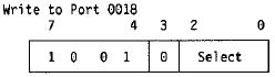
Write Transfer Count
This command loads each transferred data byte into the appropriate byte of the Transfer Count register.
The DMA channel is specified in the Select field.
Read Transfer Count
This command returns the content of the Transfer Count register in byte increments. The DMA channel is specified in the Select field.
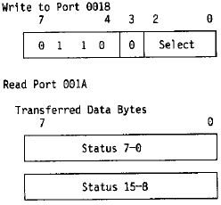
Read DMA Status
This command returns each byte of the DMA Status register and clears that byte of the DMA Status register (the byte is set to hex 00).
The Select field does not affect this command and should be set to 0.
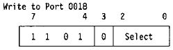
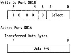
Read or Write DMA Mode
The read command returns the content of the DMA Mode register. The write command loads the transferred data byte into the DMA Mode register.
The DMA channel is specified in the Select field.

Read or Write Arbitration Level
The read command returns the contents of the Arbitration Level register. The write command loads the transferred data byte into the Arbitration Level register.
The DMA channel is specified in the Select field. Only DMA channels 0 and 4 support programmable arbitration levels; all other values of the Select field are reserved.
PIO Programming Model
Each of the eight DMA channels can be programmed independently and can operate concurrently. The DMA controller accepts commands only from the system master and accepts commands to a DMA channel regardless of whether the channel is transferring data or not.
Initialization
The following steps are performed to initialize a DMA channel:
1. Disable the DMA channel (set the Mask field to 1)
2. Load operational-control registers, if required
3. Load the transfer-control registers with the appropriate values
4. Enable the DMA channel (set the Mask field to 0)
The following is an example showing the programming of DMA channel 2 using the PIO interface commands. In this example, we want to transfer data from an I/O address (hex mmnn) to a memory location starting at an address (hex xxyyzz) and counting up a specific number of bytes (hex aabb).
Program Step;Address/Data
Set mask;0018h, 92h
Write l/O address;0018h, 02h
(hex mmnn);001Ah, nnh
;001Ah, mmh
Write memory address;0018h, 22h
(hex 00xxyyzz);001Ah, zzh
;001Ah, yyh
;001Ah, xxh
Write transfer count;0018h, 42h
(hex 00aabb);001Ah, bbh
;001Ah, aah
Write DMA mode;0018h, 72h
;001Ah, 0Dh
Reset mask 0018h, A2h
Termination
lf a DMA transfer is terminated before the terminal count has been reached, the DMA channel must be disabled. Disabling the channel ensures that the DMA channel does not enter the transfer state accidentally when arbitration levels are being shared.