DMA Controller
Appendices
Appendix A. Architecture Compliance [page 83]
Appendix B. FIFO [pages 85-93]
Appendix A. Architecture Compliance
For all PS/2 systems that are based on the Micro Channel Architecture, the DMA controller must provide support for the PIO interface (see Section 2, “PIO Interface” on page 9). For those systems with 32-bit Micro Channel connectors, the DMA controller can also provide support for the SCB interface (see Section 3, “SCB Interface” on page 33).
DMA Controller Levels
Type 1 DMA controllers provides a PIO interface and does not use a FIFO buffer.
Type 2 DMA controllers provide both PIO and SCB interfaces and implements the Data Holding register as a FIFO buffer.
Appendix B. FIFO
Basically, DMA controller operations involving a FIFO buffer are the same as those operations without a FIFO buffer. However, DMA applications that are concerned with residual data in the FIFO buffer must take the presence of the buffer into consideration when recovering from errors.
FIFO Implementation Requirements
A DMA controller that provides the SCB interface must implement the commands shown in Figure 15. These commands act on the Data Holding register and, when the Data Holding register is implemented as a FIFO buffer, these commands return values in support of the FIFO buffer. For descriptions of the commands, see “FIFO
Commands” on page 82.
Figure 15. Required Function Commands
Extended Function;Function;Command;Command Class
02;F;Restore FIFO Data;Execute
03;F;Read FIFO Byte Count;Execute
FIFO Buffer Implementation
The DMA controller that provides the SCB interface can be implemented with a FIFO buffer. When it is implemented, the FIFO buffer replaces the Holding register; the FIFO buffer must be at least four bytes (the same minimum as the Data Holding register). The additional registers and commands are described in the following.
lf residual data handling is supported, the DMA controller can implement the FIFO buffer in either of two ways:
A single FIFO buffer and FIFO Byte Count register that is shared by all channels and eight backup buffers that are used to save and restore the content of the FIFO buffer for each of the DMA channels.
Eight FIFO buffers and eight FIFO Byte Count registers, one set for each DMA channel.
FIFO Buffer Registers
The FIFO buffers are not required by the architecture. However, when implementing these buffers, existing registers need to be modified and new registers added. This section describes the changes required to implement the Data Holding register as a FIFO buffer.
The following registers must be added or changed to support a FIFO buffer.
Figure 16. Registers Affected by implementing FIFO Buffer
Register;R/W;Page Number
Additional Registers;;
FIFO Byte Count;R;80
FIFO Data;R/W;80
Changed Registers;;
Extended Function;R/W;36
DMA Mode;R;44
Transfer Count;R;47
FIFO Byte Count Register
The FIFO Byte Count register is an 8-bit, read-only register that contains the number of bytes of data in the FIFO buffer. This register can be read using the Read FIFO Byte Count command (see page 85).
FIFO Data Buffer
The FIFO data buffer is a read-write buffer that is used to temporarily store the data being transferred. For the SCB interface, the minimum size of the buffer (when implemented) is 4 bytes. The maximum size is 255 bytes.
The content of the FIFO buffer can be read with the Read FIFO Data command and can be written with the Write FIFO Data command.
Extended Function Register
This register (defined on page 36) must provide the following additional extended functions in support of the FIFO buffer.
Figure 17. Additional Extended Function Commands
Extended Function (hex);Command to Perform
02;Save or restore FIFO data
03;Read FIFO byte count
04;Read or write FIFO data buffer
DMA Mode Registers
This register (defined on page 44) defines the Residual Data Control field in support of the FIFO buffer. The field is loaded from the Residual Data Control field in the Command word during an SCB fetch operation.
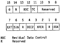
RDC The Residual Data Control field (bits 13 and 12) specifies whether the FIFO buffer will hold residual data when the DMA controller releases the channel before completing the DMA transfer operation.
Figure 18. Residual Data Control Field
RDC Field;Description
00;Residual data disabled
The FIFO buffer contains data only while controlling the system channel. All data is transferred before the system channel is released.
0 1;Residual data disabled
The FIFO buffer contains data only while controlling the system channel. All data is transferred before the system channel is released.
1 0;Residual data partially enabled
For I/O-to-memory transfers, all data is transferred before the system channel is released. However, DMA transfers from memory allow data to be held in the FIFO after the controller has released the system channel.
1 1;Residual data fully enabled
All operations allow data being transferred to be held in the FIFO buffer after the controller has released the system channel.
Transfer Count Register
When using a FIFO buffer, the Transfer Count register operates as before; however, the DMA transfer is not complete until all data is transferred from the FIFO buffer (the FIFO Byte Count register is 0).
State After Reset
After a reset operation, the state of the additional registers associated with the FIFO buffer is shown in the following table.
Figure 79. FIFO Register initialization
Register;Value;Description
FIFO Byte Count;00;FIFO empty
FIFO Data;-;FIFO empty
FIFO Backup;-;Not initialized
FIFO Commands
This section describes the commands that must be added or changed to support implementing a FIFO buffer.
Figure 20. Commands Affected by implementing FIFO Buffer
Extended Function;Function;Command;Type
Additional Commands;;;
02;F;Save or restore FIFO data;Execute
03;F;Read FIFO byte count;Execute
04;F;Read or write FIFO data;Execute
Changed Commands;;;
;D;Reset DMA controller;Immediate
0D;F;Reset DMA channel;Immediate
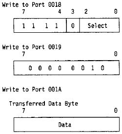
Save FIFO Data
This command moves the content of the FIFO buffer into the backup buffer for the specified DMA channel. The Select field specifies the DMA channel.
NOTE: The data byte transferred has no affect on the operation and should be set to 0.
Restore FIFO Data
This command moves the content of the backup buffer into the FIFO buffer. The Select field specifies the DMA channel.
The transferred data byte is always 00.
NOTE: This command must be performed before attempting to read the FIFO byte count or data buffer.

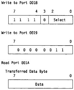
Read FIFO Byte Count
The read command returns the contents of the FIFO Byte Count register. The DMA channel is specified in the Select field.
NOTE: The restore command must be performed before attempting to read the FIFO byte count.
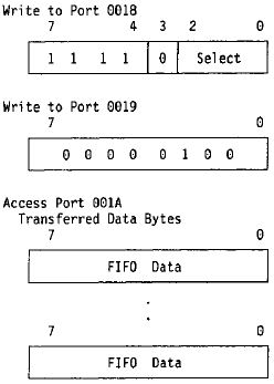
Read or Write FIFO Data
The read command returns a byte from the FIFO buffer and decreases the FIFO byte count by 1. The write command loads the transferred data byte into the FIFO buffer and increases the FIFO byte count by 1. The Select field specifies the DMA channel associated with the data being read or written.
Reset DMA Controller
In addition to the operations defined in “Reset DMA Controller” on page 64, the DMA controller using a FIFO buffer must also set the FIFO Byte Count register to hex 00.
Reset DMA Channel
in addition to the operations defined in “Reset DMA Channel” on page 64, the DMA controller using a FIFO buffer must also set the FIFO Byte Count register to hex 00 (the Backup FIFO register, if implemented, is not affected).
FIFO Operation Program Model
The following shows a programming model for operations that work with the contents of the FIFO buffer. These operations are used when an application is recovering residual data that may be in the FIFO buffer.
Reading from the FIFO buffer
Issue the Restore FIFO Buffer command
Issue the Read FIFO Byte Count command
if byte count is greater than 0
- Then issue the Read DMA FIFO Data command for byte count iterations.
- Otherwise, the FIFO buffer is empty or does not exist.
NOTE: This procedure does not require that the programmer know the actual size of the FIFO buffer or even if one is implemented.
Writing to the FIFO buffer
Determine the state of the FIFO buffer
- If state of the FIFO buffer is unknown, reset the DMA channel.
- Otherwise, read the FIFO byte count to ensure that the FIFO buffer is empty or at a know state.
- Write data to the buffer up to the actual size of the FIFO buffer.
- Save the FIFO data, specifying the DMA channel.
NOTE: This procedure requires that the programmer know the size and residual support provided in the FIFO implementation.