A certain number of generic tools are supplied with DMU Space Analysis. These tools let you measure the minimum distance and angle between geometrical entities or points, properties associated to selected items, and the moments of inertia, density and mass of items.
You can also measure the length, radius and angle of an arc drawn through three points as well as measure distances, angles and the radius on 2D documents of both pixel and vector type.
To learn more about, read the following:
Measure
Between, Item and Inertia commands
Measure Between, Measure Item and Measure Inertia offer a complete set of exact measurements on and between products, parts and features, as well as on all types of 3D formats, including in Visualization mode and for CGR files.
These commands also offer an approximate mode for faster calculation.
Measure Between and Measure Item are useful when performing sectioning operations to, for example, annotate the generated section.
To do so, select the Keep Measure check box.
Notes:
-
When performing a measure operation on a Part or a CATProduct document, all Part bodies are taken into account in the measure calculation. So even if you have an hybrid body built with boolean operations, all the parts and bodies will be taken into account for the measure item calculation.
-
Exact measures are also available on V4 skins.
In the No Show space, measure commands are not accessible.
Shading with
Edges
To get the most out of these tools, set the Render Style to Shading with Edges. The various command options work differently depending on the selected render style.
Modifying the Color, Line thickness
and Text color of the Measure Result
To make it easier to read your result, you can specify different properties for measure result. This is done via the Properties command or via the Measure Tools tab in Tools > Options > Digital Mockup->Parameters and Measures.
Properties Command
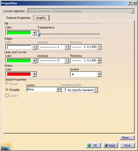
The Properties command lets you change the color, line width, the points color and text color of the current measure result (under Lines and Curves in Graphics tab).
To access properties:
-
Right-click the specification tree measure feature and select Properties.
-
In the dialog box, click the Graphic tab.
-
Set the color, the line thickness and points color as desired.

Tools > Options
You can also change these properties via Measure Tools tab in Tools > Options
To do so:
-
Select Tools > Options > Digital Mockup >Parameters and Measures
-
Set the color, text color for the measure in the Graphic Properties area.

To return to the initial colors, select Reset icon in the left-hand box
Refer to Measures Tools in DMU Space Analysis Customizing section
Note: Modifying the product color has no effect on the measure color which is therefore not modified.
Measures (of all types)
in Scene Context
Precisions on Automatic update in product Setting:
- If the automatic update in product check box in Tools > Options > Parameters and Measures > Measure Tools is selected, measures made using Measure Between, Measure Item, Measure Inertia and Measure Arc through Three Points are updated in a scene context.
- If the automatic update in product check box in Tools > Options
> Parameters and Measures > Measure Tools is cleared, measures made
using Measure Between, Measure Item, Measure Inertia and Measure Arc
through Three Points are not updated in scene context. The measure icon
does not reflects the not up to date state in the specification tree.


For more information refer to Scenes section in DMU Navigator User's Guide
Measure Links
Important:
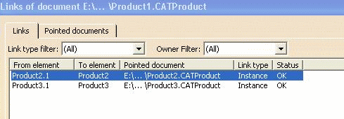
- Measure links are not exposed thus they do not appear in the Edit > Links dialog box.
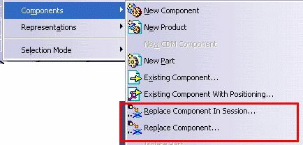
- Measures are not taken into account by the Replace command.
- Side effect: The measure status (identified in the specification tree with specific icons updated/not updated) cannot be controlled, i.e. the status can be valid whereas it should not be.
Therefore when
using the replace functionality accessible either by the contextual menu
or using Edit > Components (Replace Component or replace in
Session) it is not possible to ensure the links will be updated.
 |
Let's consider a measurement made between two products (namely product2 and Product3), when displaying Edit > links you notice the measure link is not listed because the measure link is not exposed:
 |
If you select the measure either in the specification tree or in the geometry area, the following message is displayed:
 |