in your Machining program.
More information about the operating mode is available in 4-Axis Curve Sweeping Operation.
To create a 4-Axis Curve Sweeping operation, click
More information can be found in Selecting Geometry.
Select the machining strategy tab
![]() and choose a
guiding strategy for this operation:
and choose a
guiding strategy for this operation:
Then set the following strategy parameters according to the desired
machining:
Specify the tool
![]() to be used,
feeds
and speeds
to be used,
feeds
and speeds ![]() ,
and NC macros
,
and NC macros
![]() as needed.
as needed.
4-Axis Curve Sweeping: Strategy Parameters
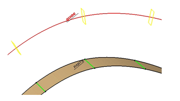
The 4-Axis Curve Sweeping is done along a planar guide.
The stepover is computed from this guide.
The tool axis is constant in each machining plane (displayed in yellow
below) and normal to the guide.
|
|
|
You need to select a Guide
using the sensitive icon:
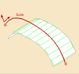
This guide:
- is selected in the 3D viewer,
- must be planar and continuous,

Straight lines are not allowed. - can be restrained by limiting points, selected in the 3D viewer using
the sensitive icon,

You can: - click the limiting point in the sensitive icon and select a point in the 3D viewer,
- or right-click the limiting point in the sensitive icon and
select On guide in the contextual menu.
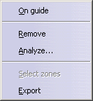
A red dot appears on the Guide. You can drag it to the required position.
- is oriented by three directions:
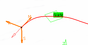
- M: Machining direction, tangent to the guide at one of its ends.
- A: Axis direction of the tool, normal to the guide in its plane.
- S: Stepover side, to define where the first pass starts.
- all three directions can be inverted by clicking the corresponding arrow.
Once the Guide is selected, the arrows
![]() in the sensitive icon turn green.
in the sensitive icon turn green.
Click them to display the
Starting Directions dialog box.
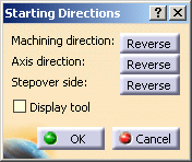
Clicking Reverse is the same as clicking the corresponding arrow
in the 3D viewer.
You can select the Display tool check box to display the tool in
the 3D viewer.
4-Axis Curve Sweeping: Machining Parameters

Tool path style
Indicates the cutting mode of the operation:
- Zig Zag: the machining direction is reversed from one path to the next
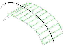
- One way: the same machining direction is used from one path to the
next.

Machining tolerance
Specifies the maximum allowed distance between the theoretical and computed tool path.
4-Axis Curve Sweeping: Radial Parameters

Distance on guide

Defines the distance between paths, on the Guide.
Stepover side
Can be set to the Left or to the Right of the Machining direction.
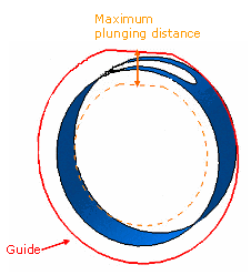
Max. plunge distance
This check box is not selected by default.
In some cases, unwanted paths might be generated.
For example, in the hole shown below, the tool might plunge to the bottom of
the part.
You can select the Max plunge distance and enter a value for it,
to prevent unwanted machining paths.
4-Axis Curve Sweeping: Tool Axis Parameters

Lead angle
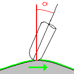
Defines the lead angle in the direction of motion.
4-Axis Curve Sweeping: HSM Parameters

Corner radius
Defines the radius of the rounded ends of passes.
The ends are rounded to give a smoother path that is machined much faster.
4-Axis Curve Sweeping: Geometry
You can specify the following Geometry:
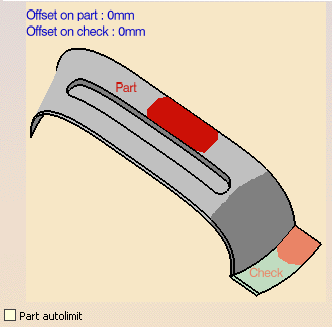
- Part (mandatory) with possible Offset on Part.
- Check elements (optional) with possible Offset on Check.
Offset groups and
Geometrical zones are supported, machining areas are not.
You can also select the
Part autolimit
check box.
|
|
|
4-Axis Curve Sweeping: Tools
Only end mill tools are available.
4-Axis Curve Sweeping: Feeds and Speeds
In the Feeds and Speeds tab page, you can specify feedrates for approach,
retract and
machining as well as a machining spindle speed.
Feedrates and spindle speed can be defined in linear or angular units.
A Spindle output checkbox is available for managing output the SPINDL
instruction in the generated NC data file.
If the checkbox is selected, the instruction is generated. Otherwise, it is
not generated.
Feeds and speeds of the operation can be updated automatically according
to tooling data and
the Rough or Finish quality of the operation.
This is described in
Update
of Feeds and Speeds on Machining Operation.
4-Axis Curve Sweeping: NC Macros
You can define transition paths in your machining operations by means of NC Macros.
All types of macros are available with two exceptions:
- Clearance is always set to Optimized,
- Straight is not available for Between passes Link.
