Isoparametric machining is an operation which allows you to select strips of faces and
machine along their isoparametrics.
Click Isoparametric machining
![]() then select the geometry to be machined
then select the geometry to be machined
![]()
and the collision
checking parameters:
- whether the checking is done on the cutting part of the tool or on the tool assembly,
- make the Part active and set the Accuracy and Allowed gouging
- and set the Accuracy and Allowed gouging on the Check.
A number of
parameters are available in the machining strategy tab![]() :
:
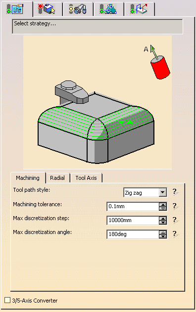
- In the Machining tab to define:
- the Tool path style,
- the Machining tolerance,
- the Max discretization step,
- the Max discretization angle
- and to activate the 3/5-Axis Converter option.
- in the Radial tab :
- to define the Radial strategy,
- or activate the Skip path option,
- to define the Start extension or the End extension.
- in the Tool Axis tab to define:
- the Tool axis mode.
Specify the
tool to use ![]() (the tools that
can be used with this type of operation are
(the tools that
can be used with this type of operation are
end mill ![]() ,
face mill
,
face mill ![]() , conical
mill
, conical
mill ![]() and T-slotter
and T-slotter
![]() tools), the
feedrates and spindle speeds
tools), the
feedrates and spindle speeds ![]() .
.
You can also define transition paths in your machining operations by
means of NC macros
![]() as needed.
as needed.
Only the geometry is obligatory, all of the other requirements have a
default value.
Isoparametric Machining: Strategy Parameters
Isoparametric Machining: Machining Parameters
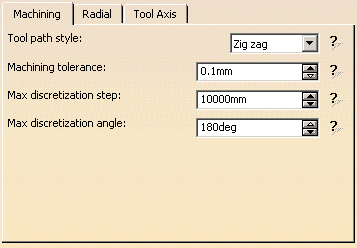
Tool path style
- One-way: the tool path always has the same direction during
successive passes and
returns to the first point in each pass before moving on to the first point in the next pass. - Zig-zag: the tool path alternates directions during successive passes.
Machining tolerance
Maximum allowed distance between the theoretical and computed tool path.
Consider it to be the acceptable chord error.
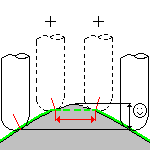
Max discretization step
Ensure linearity between points that are far apart.
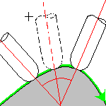
Maximum angle between two consecutive points that the machine is able to
achieve.
- The Maximum discretization step and Maximum discretization angle influence the number of points on the tool path.
- The values should be chosen carefully if you want to avoid having a high concentration of points along the tool trajectory.
- These parameters also apply to macro paths that are defined in
machining feedrate.
They do not apply to macro paths that do not have machining feedrate (RAPID, Approach, Retract, User, and so on). - Default value for Maximum discretization step is 100 m.
- Default value for Maximum discretization angle is 180 degrees.
Isoparametric Machining: Radial Parameters
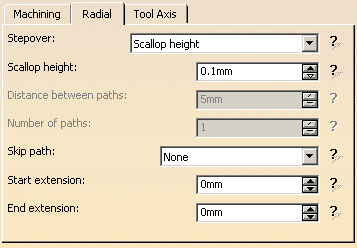
Stepover
Defines how the distance between two consecutive paths is to be computed.
You can choose to define it by
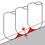
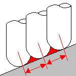
- Scallop height, i.e. the maximum scallop height between two
consecutive tool paths in a radial strategy.
- Distance on part, i.e. the maximum distance measured
between two consecutive tool paths on
the part in a radial strategy.
- or the Number of paths that the tool makes on the part in a
radial strategy.
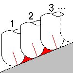
The choice of one type activates the corresponding parameter.
In Zig zag mode, the tool path generated always starts from
point 1 to point 2 and
finishes from point 3 to point 4.
For this purpose, an additional path may be added on top of the radial
strategy criterion.
In One way mode, all paths are oriented from point 1 to point
2.
For this purpose, the tool path may finish on point 3 or point 4.
Those rules also applies when Skip path or Startextension/End extension are active.
Skip path
You may also choose to skip (not machine) the first or last path or both
of
the tool path in all three of the radial strategies.
Start extension
Specifies the length of an additional machined area located before the
first path on part.
This value can be either positive (the global machined area is extended) or
negative (the global machined area is shrunk).
End extension
Specifies the length of an additional machined area located after the
last path on part.
This value can be either positive (the global machined area is extended) or
negative (the global machined area is shrunk).
Example:
- Case 1: Tool path generated with the Radial strategy set to
Number of paths=5.
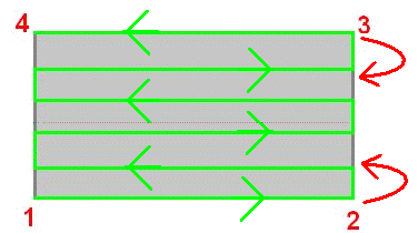
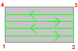
- Case 2: the same with Skip path set on First and
last.
Isoparametric Machining: Tool Axis Parameters
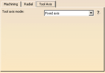
Tool axis mode
Define the tool axis guidance mode:
- Fixed axis: The tool axis remains constant for the
operation.
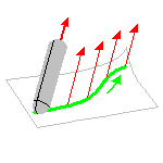
- Interpolation with
- Allowed tilt angle.
The tool axis is interpolated between two selected axes.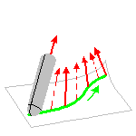
- Allowed tilt angle.
- Lead and tilt with
- Guidance type,
- Lead angle,
- Min lead angle and Max lead angle and
- Allowed tilt angle.
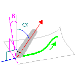
in the forward tool motion and with respect to a given tilt angle in the perpendicular direction
of this forward motion. - Optimized lead with
- Min lead angle and Max lead angle and
- Min heel distance.
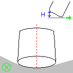
The tool axis is allowed to vary from the specified lead angle within an allowed range.
The allowed range is defined by Minimum and Maximum lead angles.
The back of the cutter is to be kept clear of the part by means of a Minimum heel distance.Optimized lead works as follows:
- lead defined as minimum to fit the part curvature
- lead increases if necessary to respect the Minimum heel distance.
- If the required lead is outside the allowed range,
the tool position will not be kept in the tool path. - The maximum material removal is obtained when the tool curvature
along
the trajectory matches the part curvature.
- 4-axis lead/lagg with
- Lead angle.
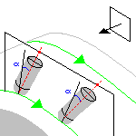
The tool axis is normal to the part surface with respect to a given lead angle in the forward direction
and is constrained to a specified plane. The tool axis is computed like in Lead and Tilt mode
and then projected into the constraint plane.
- Lead angle.
- 4-Axis Tilt with
- Tilt angle,
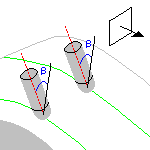
- Lead angle.
- Tilt angle,
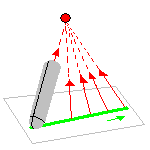
- Thru a point.
The tool axis passes through a specified point.
- Normal to line.
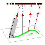
Isoparametric Machining: Geometry
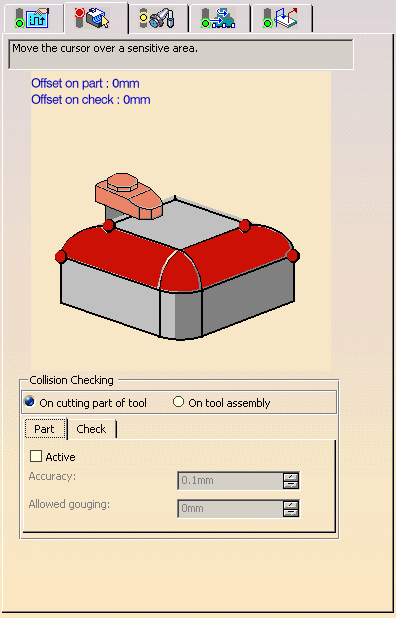
You can specify the following geometry:
- Part with possible offset on the part (double-click the label).
- Points on part to define the direction of isoparameters.
- Check element with possible offset on the check element
(double-click the label).
The check is often a clamp that holds the part and therefore is not an area to be machined.
|
|
|
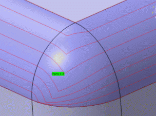
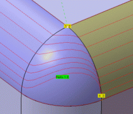
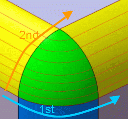
Recommended methodology:
Create blue fillet first, then the yellow fillet to set the isoparametrics
correctly.
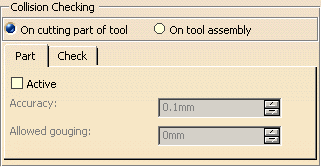
It can be performed on check and part elements with the tool
assembly
On tool assembly,
that is, the complete shape of the cutter plus its holder)
or the cutting part of the tool (On
cutting part of tool, red part of following tools).
To save computation time you should use tool assembly only
if the geometry to be checked
can interfere with the upper part of the cutter.
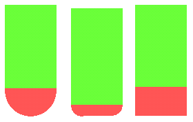
Isoparametric Machining: Collision Checking - Part parameters
Active
To activate collision checking on part elements, you must select the
Active check box.
This is useful in the following cases:
- Concave part machined with Fixed tool axis mode.
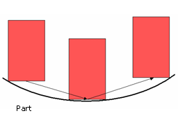
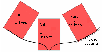
- Concave and non smooth part milled with 0°
Lead angle.
Note that Allowed gouging, part must be set to a non zero value,
otherwise a "Nothing to Mill" message may be issued.
Collision checking on part elements is not useful in the following cases:
-
Convex part machined with ball, flat or filleted ended tool or with Fixed or Variable tool axis mode.
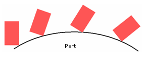
- Concave part milled with 0°
Lead angle. A "Nothing to Mill" message may be issued.
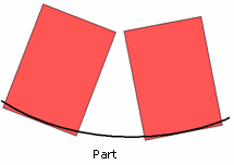
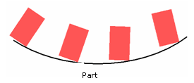
- Ruled and smooth part with Optimized Lead tool axis mode.
Minimum heel distance will keep the back of the cutter clear.
Maximum precision error to be accepted in the respect of the part (or check) with its thickness.
Maximum cutter interference with the part (or check) during macro motions.
Isoparameteric Machining: Collision Checking - Check Parameters
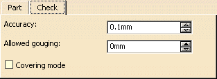
The parameters involved for check elements (such as fixtures) are:
Check (or Fixture) Accuracy:
defines the maximum error to be accepted with respect to the fixture with
its offset.
Setting this parameter to a correct value avoids spending too much
computation time
to achieve unnecessary precision.
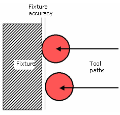
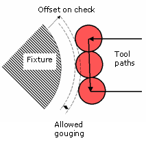
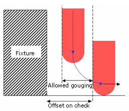
Allowed gouging: maximum cutter interference with the fixture
during "linking passes"
(including approach and retract motion).
- This illustration shows return motion with no macro or jump.
- This illustration shows return motion with macro between path and
fixture.
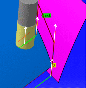
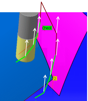
Select this option to optimize air cuts due to collision with the check.
In the example below, a Return in Level macro has been defined.
- The Covering mode is not selected:
- The Covering mode is selected, the air cut is reduced:
- You can apply a positive or negative offset on the check,
- The Covering mode applies to the tool path (in green), not to the macro motions (in red),
- The Covering mode applies to the whole set of check surfaces defined in the machining operation
