The 3/5-Axis Converter is a process that
can be included in the computation of the tool path to convert a 3-axis machining operation into a 5-axis one to avoid collisions.
Two axis strategies are available to
- modify the tool axis of a tool path resulting from a machining
operation without changing its contact point either by changing a 3-axis
tool path into a 5-axis tool path or by modifying a 5-axis tool path,
- or avoid the collisions of the tool or the tool assembly within a 5
axis machining strategy,
- collision checking is performed with the selected geometry, not with
the rough remaining from the previous operation.
It is available for the following commands:
- Roughing,
- Sweeping,
- Pencil,
- ZLevel,
- Contour-driven,
- Spiral Milling,
- Isoparametric Machining,
- Profile Contouring,
at the bottom of the machining strategy tab.
Select the check box 3/5-Axis Converter to activate this
option.

More... starts the 3/5-Axis Converter dialog
box with:
- a machining strategy tab
 with: with:
- a global modification tab and
- a collisions checking tab.
- a macro tab

Global
Modification
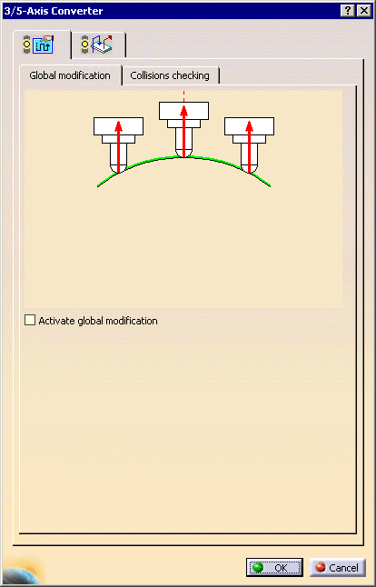
By default, the global modification is not active.
Select the Activate global modification check box to
replace all the tool axes of the tool path with the one
selected in the Tool axis mode list.
The dialog box turns into the following:
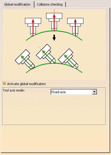
The upper part of the graphic zone of the dialog box represents the initial
tool path whereas the lower part represents the modified tool path.
Tool axis mode
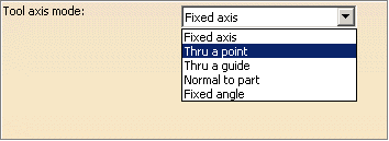
Lets you select a new tool axis mode from the drop-down list.
- Fixed axis
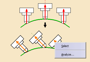
Place your cursor over one of the tool axis arrow and choose
Select
to define the tool axis.
Analyze starts the
Geometry Analyser.
- Thru a point
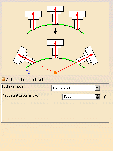
The tool axis passes through a specified point. The tool axis can be
oriented To the point or From the point (Click
the label To to switch to From and vice versa).
Click the point in the sensitive icon and select a point in the graphic
area.
- Thru a guide
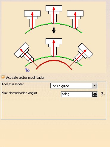
The tool orientation is controlled by a geometrical curve (guide), that
must be continuous. An open guide can be extrapolated at its extremities.
Click the red curve in the sensitive icon and select a curve in the 3D
viewer.
The tool can be orientated From or To the guide (Click
the label To to switch to From and vice versa).
- Normal to part
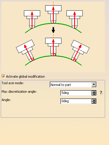
The tool axis is normal to the part
Angle
Lets you specify a possible frontal angle between the tool axis and the
normal to the part.
- Fixed angle
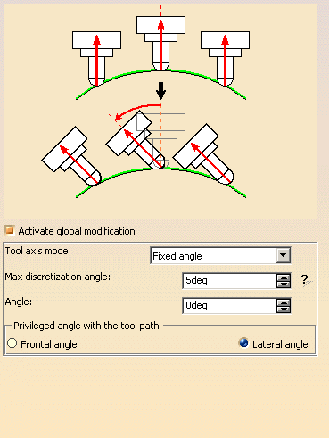
The new tool axis forms an angle with the initial tool axis.
Angle
Lets you specified this fixed angle.
Privileged angle with the tool path
Defines the angle a plane defined by the direction of motion (Frontal angle)
or in a plane normal to the direction of motion (Lateral angle).
Max discretization angle
Specifies the maximum angular change of tool axis between tool positions.
It is used to add more tool positions (points and axis) if value is
exceeded.
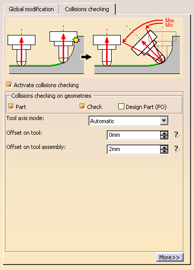
The collision checking is active by default.
Clear the check box if you do not want to perform a collision checking.
The left part of the graphic zone in the dialog box represent the initial
tool path whereas the right part represents the modified tool path that will
avoid collisions.
Decide on which geometry you want to perform the collisions checking:
- Part (selected by default),
- Check (selected by
default),
- or Design Part of the Part Operation (not selected by
default)
Note that in a Profile contouring operation, you cannot select a part.
You must select the Design Part (PO) check box and make sure it
exists in the Part Operation.
Tool axis mode
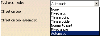
Lets you select a new tool axis mode from the drop-down list. It will be
applied to the points in collision found.
- None
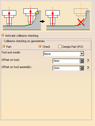
The tool axis is not modified, the tool path stops
before the collision
point, and the corresponding portion of tool path is removed.
- Fixed axis
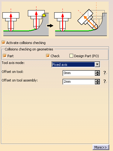
See Fixed axis above.
- Thru a point
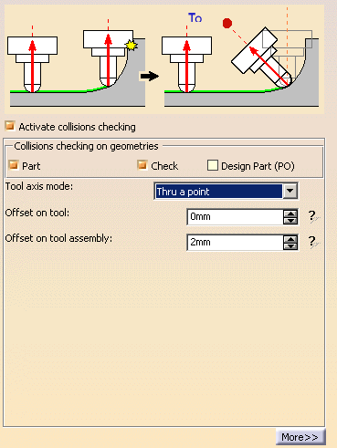
See
Thru a point above.
- Thru a guide
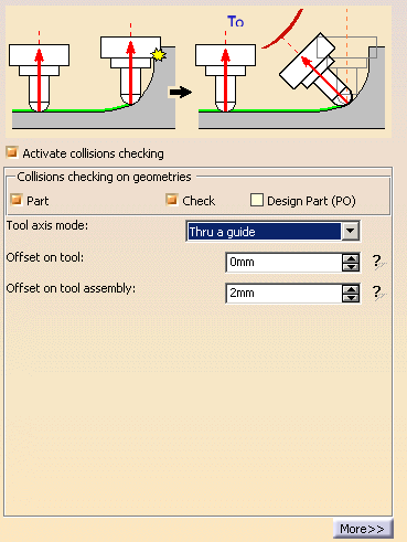
See
Thru a guide above.
- Normal to part
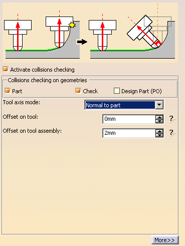
See
Normal to part
above.
- Fixed angle
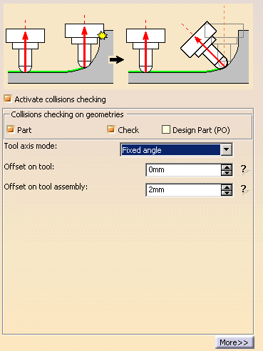
See
Fixed angle above.
- Automatic
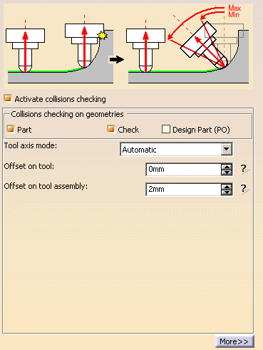
The tool axis is automatically computed to avoid collisions.
You can access more parameters for the above tool axis modes by clicking
more:
- For all tool axis modes except None:
Max discretization angle
Specifies the maximum angular change of tool axis between tool positions.
It is used to add more tool positions (points and axis) if value is
exceeded.
Minimum length
Specifies the minimum distance that must exist between two collision
points to allow the modification of the tool axis between those two
points.
- For the tool axis mode Normal to part:
Angle
Lets you specify a possible angle between the tool axis and the normal to
the part.
- For the tool axis mode Fixed angle:
Angle
Lets you specified the fixed angle.
Privileged angle with the tool path
Defines the angle a plane defined by the direction of motion (Frontal angle)
or in a plane normal to the direction of motion (Lateral angle).
- For the tool axis mode Automatic:
Minimum angle and Maximum angle defines the range within
which the tool axis can vary.
Step angle defines the computation step used to find the
optimal angle to avoid collisions. The smaller the Step angle,
the longer the computation time.
Offset on tool
Defines the offset applied on the tool to
avoid collisions.
Offset on assembly
Defines the offset applied on the tool assembly
to avoid collisions.
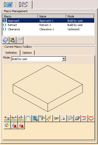
When collision points found on the tool path are removed, the tool path
must be closed. This tab lets you do that with Approach, Retract and
Clearance macros.
 |