Click Sweeping
![]() , then
the geometry of the part
to machine
, then
the geometry of the part
to machine ![]() ,
,
A number of strategy parameters
![]() are available in:
are available in:
- the Machining tab to define:
- the Tool path style,and the Plunge mode if necessary,
- the Machining tolerance,
- and activate the Reverse tool path, the Max Discretization (with its step and Distribution Mode) and the 3/5-Axis Converter options.
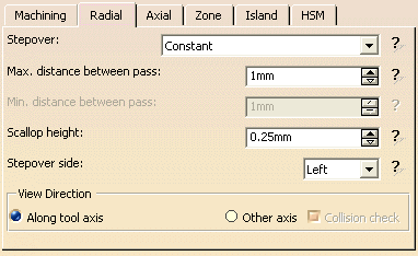
- the Radial tab to define:
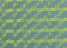
- the Stepover type with the Maximum or Minimum distance between pass and the Scallop height,
- the Stepover side,
- the View direction Along the tool axis or along another axis.
- the Axial tab to define:
- the Multi-pass,
- the Number of levels,
- the Maximum cut depth,
- the Total depth,
- the Zone tab to define:
- the Island tab to:
- define the Feedrate length,
- activate the Island Skip and Direct options.
- the HSM tab.
Specify the
tool to be used
![]() ( you have
the choice of end mill
( you have
the choice of end mill ![]() or conical
or conical ![]() tools
for this operation),
tools
for this operation),
the feedrates and spindle speeds ![]() .
.
You can also define transition paths in your machining operations by
means of NC macros
![]() as needed.
as needed.
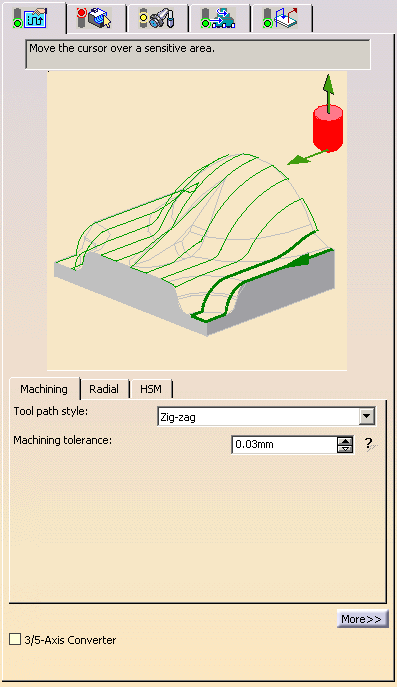
Sweeping: Strategy tab
-
The Sweeping strategy parameters are distributed into 5 tabs.
By default, all 5 tabs are displayed with all their parameters.
However, current operations only require a reduced list of those parameters. -
Click <<Less to display only those current parameters:
-
the Axial, Zone and Island tabs are hidden,
-
in the Machining tab, Reverse tool path, Max Discretization
and its Step and Distribution Mode and Plunge Mode are hidden, -
in the Radial tab, View direction is hidden.
-
-
Click More>> to re-display all parameters.
-
You can also use the modal option User Interface Simplified mode in the
Tools -> Options -> Machining -> Operation tab.
-
By default, all tabs and all parameters are displayed:
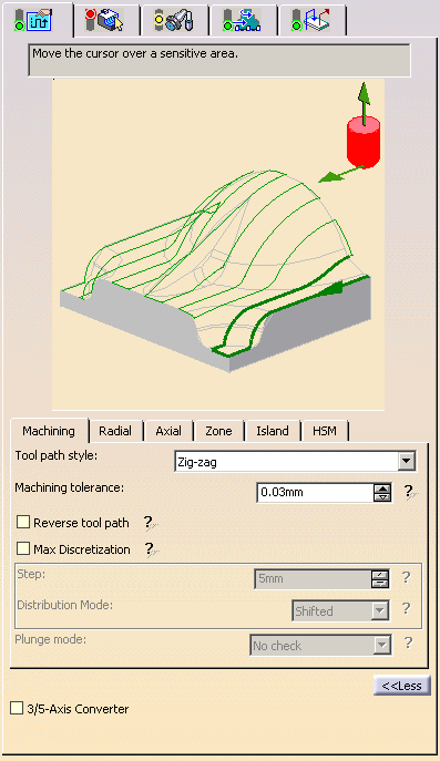
- Click <<Less to display a reduced list of tabs and
parameters:
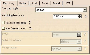
Sweeping: Machining parameters
-
By default, or when the More>> button is pressed:
-
When the <<Less button is pressed:
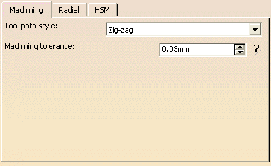
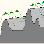
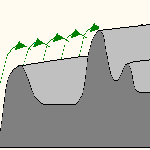
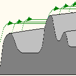
Tool path style
- One-way next: the tool path always has the same direction
during successive passes and
goes diagonally from the end of one tool path to the beginning of the next. - One-way same: the tool path always has the same direction
during successive passes and
returns to the first point in each pass before moving on to the first point in the next pass. - Zig-zag: the tool path alternates directions during successive passes.
Plunge mode
Hidden when the <<Less button is pressed.
If you have selected a one-way Tool path style, select the Plunge mode:
- No check: the tool can plunge and rise with the surface,
- No plunge: the tool cannot plunge,
- Same height: the tool does not plunge but will not stop
when it encounters a peak.
Machining tolerance
Maximum allowed distance between the theoretical and computed tool path.
Consider it to be the acceptable chord error.
Reverse tool path
Hidden when the <<Less button is pressed.
Max Discretization
Hidden when the <<Less button is pressed.
For some surfaces, such as flat surfaces, the tool path can suffer from a
lack of points.
By setting the maximum discretization distance (Step),
the gaps will be filled by the exact surface points
resulting in a better distribution of points, a smoother tool path and
then a better machining quality.
In addition, two Distribution Modes
are available to improve the quality of the machined surface:
|
|||
|


- This parameter is available with a spherical tool only.
- The number of points of the tool paths will vary with the distribution mode.
Sweeping: Radial parameters
-
By default, or when the More>> button is pressed:
-
When the <<Less button is pressed:
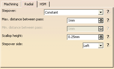
Stepover
Use the list to select either:
- Constant: Has constant
stepover distance defined in a plane and projected onto the part.
You can modify the stepover distance.
You can modify:
- the Maximum distance between passes
- and the Scallop height
If you enter a Scallop height, the Max. distance between pass is computed automatically.
- the Maximum distance between passes
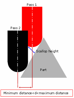
- Via scallop height:
The stepover is computed from the scallop height you have set,
within the range defined by Max. distance between pass and Min. distance between pass.
For example, filled holes or vertical walls outside the limiting contour influence the stepover computation and
may generate useless paths.
The by-pass consists in not selecting these useless geometries to compute the toolpath.
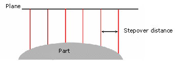
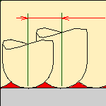
Maximum distance between pass
- Stepover distance if you have selected Constant as the
value
-
or the maximum stepover distance if you chose Via Scallop height.
Minimum distance between pass
Minimum stepover distance if you chose Via Scallop height.
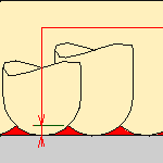
Scallop height
Value that you define for the maximum allowable height of the crests of material left uncut after machining.
Stepover side
Can be left or right and is defined with respect to the machining direction.
View Direction
- Hidden when the <<Less button is pressed.
- Use Along tool axis
when you want to machine along the axis you have selected
(or along the default axis). - Other axis can only be
used with a ball-nose tool.
When it is selected, the axis/direction icon lets you define a second axis
(the other axis - the one pointing up to the left).

Activating Other axis displays a button for
collision checking.
When this is turned on, all of the points where the toolholder would have
collided
with the part are displayed on the tool path (after Replay).
Sweeping: Axial Parameters
This tab is hidden when the <<Less button is pressed.
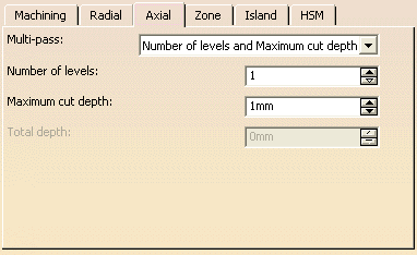
Multi-pass
Use the list to select the mode of input:
- Maximum cut depth and total depth: Enter the
Total depth and the
Maximum cut depth
- Number of levels and total depth: Enter the
Number of levels and the
Total depth.
- Number of levels and Maximum cut depth: Enter the
Number of levels and the Maximum cut depth.
Only two can be selected at time, you select which two via the input mode
choice.
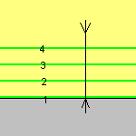
The example below was obtained with 3 levels at a cut depth of 5mm,
but could just as easily have been obtained by:
- A cut depth of 5mm and a total depth of 15 mm,
- or a total depth of 15 mm and 3 levels.
Sweeping: Zone parameters
This tab is hidden when the <<Less button is pressed.
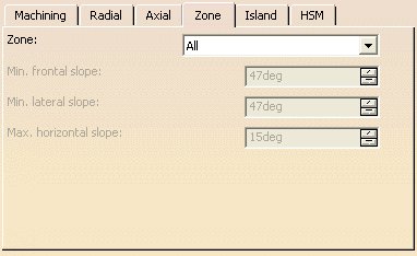
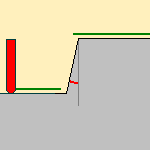
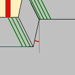
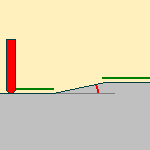
Zone
Defines which parts of the part or machining area you wish to machine:
- Frontal walls: frontal surfaces of the part are machined,
- Lateral walls: lateral surfaces of the part are machined,
- Horizontal zones: horizontal surfaces of the part are machined.
Sweeping: Island parameters
This tab is hidden when the <<Less button is
pressed.
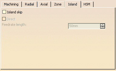
Island skip
Select this check box if you want to use intermediate approaches and
retracts
(i.e. those that link two different areas to machine and that are not at the
beginning nor the end of the tool path).
- With Island skip selected:
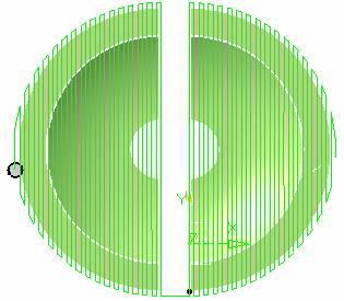
-
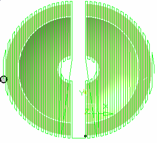
With Island skip cleared:
Direct
- With the Direct check box selected, the tool is not allowed to rise on intermediate approaches and retracts.
- Whit the Direct check box cleared, the tool will rise to 10 mm on intermediate approaches and retracts.
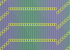
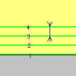
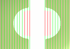
Feedrate length
Distance beyond which tool path straight lines will be replaced by
intermediate approaches and retracts.
In the picture below, the Feedrate length was set to 45 mm.
Note that the gaps that were less than 45 mm are crossed by a straight line
tool path and
those that are greater than 45 mm are crossed with a standard intermediate
tool path with an approach and a retract.
Sweeping:High Speed Milling tab
All parameters remain displayed in the <<Less mode.
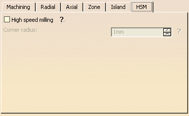
Corner radius
Defines the radius of the rounded ends of passes.
The ends are rounded to give a smoother path that is machined much faster.
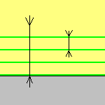
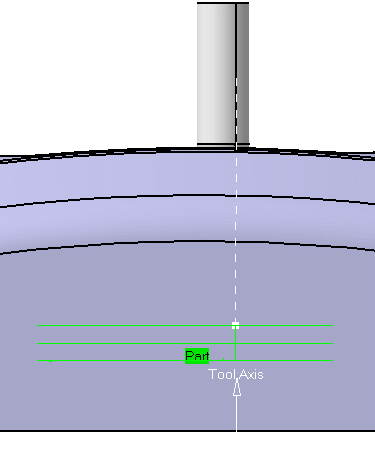
Sweeping: Geometry
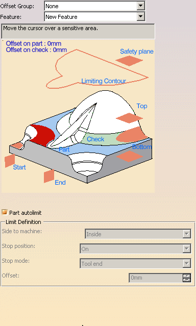
You can specify the following geometry:
- Part with possible Offset on Part (double-click the label).
- Check elements with possible Offset on Check (double-click
the label).
The check is often a clamp that holds the part and therefore is not an area to be machined.
The tool path quality is improved along "between paths" if check surfaces are selected.
- Area to avoid if you do not wish to machine it (the small light brown corner near the part selection area).
- Safety plane.
The safety plane is the plane that the tool will rise to at the end of the tool path in order to avoid collisions with the part.
You can also define a new safety plane with the Offset option in the safety plane contextual menu.
The new plane will be offset from the original by the distance that you enter in the dialog box
along the normal to the safety plane.
If the safety plane normal and the tool axis have opposed directions, the direction of the safety plane normal is inverted
to ensure that the safety plane is not inside the part to machine.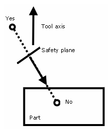
Note that when an Approach/Retract macro is set to None, the safety plane is not reached.
See the Macros Parameters chapter for more information. - Top plane which defines the highest plane that will be machined on the part,
- Bottom plane which defines the lowest plane that will be machined on the part,
- Limiting contour which defines the outer machining limit on
the part.
You can also activate the Part autolimit option, with the Side to machine, Stop position,
Stop mode and Offset parameters.
If you are editing a rework or a slope area, an additional
information is displayed,
indicating which type of subset you are working on.
This field is not editable (you can not go from one subset to another).
When pressed, gives the details on the parameters that were defined with the rework area.
Please refer to the Basic Task - Selecting Geometric Components to learn how to select the geometry.
Appears when
invalid faces have been detected.
This message disappears when you close the dialog box or when the next
computation is successful.
![]()
Appears when invalid faces have been detected and when you have decided
to ignore them.
This message remains displayed as a warning.
Click the text to switch from one status to the other.