These modes are
available for all 3 Axis Surface Machining operations with
the exception of the Roughing operations where only the numeric mode is
available,
and the ZLevel operations where the two modes below are proposed, but with a
limited number of motion types to avoid inconsistencies:
You can insert PP Words as you define the
macros.
PP words can be inserted and edited in macros of the following
operations:
- Sweep Roughing, Sweeping, Z-level (for Approach, Retract, Linking and Between Passes),
- Pencil, Contour-driven, Spiral milling (for Approach, Retract, and Linking),
- Roughing, Prismatic Roughing, Power Machining and Cavities roughing (Pre and Post motions).
-
Go to the macros tab
 .
.You are offered three methods to add the macros:
-
the catalog method. Click
 to
save a macro in a catalog and
 to read a
macro from a catalog.
For more information on how to save or load an existing macro, please refer to Build and use a macros catalog. -
the graphic method, using macros proposed by the application,
-
the numeric method, by defining yourself the macros.
In the Macro Management frame, you will find the list of the type of macro that can be defined
for the current machining operation.
And for each type, you will find the Name of the macro and the machining Mode affected to this macro.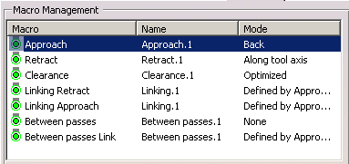
-
Graphic mode:
-
By default, you are offered a graphic mode, with macros proposed by the application,
the parameters of those you can edit.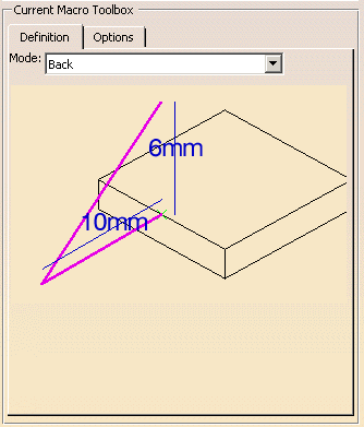
-
Select the Approach macro in the list above.
In the Definition tab, select a machining mode from the list:
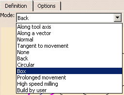
The viewer in the dialog box is updated accordingly, with pre-defined parameters:
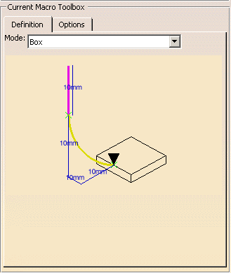
The current macro path is colored violet.
The graph displayed in the viewer of the dialog box is a generic representation of a macro mode.
It is not the true representation of the macro you are using or defining.
To check the tool path, click Replay. -
With the cursor in the viewer window of the dialog box, you can zoom in and out and pan the paths.
-
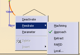
Place your cursor on a portion of the macro path. Right-click to display the contextual menu.
-
Deactivate: Deactivates the selected macro path,
-
Activate: Activates a path that was previously deactivated,
-
Feedrate: Allows you to modify the feedrate type associated to the selected macro path by
making a selection in the sub-menu. If Local is selected, you can assign a local feedrate value. -
Parameter: Tunes up the parameters of the macro in the dialog box that is then displayed.
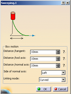
The parameters dialog box can also be launched by double-clicking a portion of the path in the viewer.
-
-
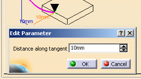
Double-click a label in the viewer to start the edition dialog box of the corresponding parameter.
-
Once you are satisfied with the settings of a macro, select another one to tune up,
or click OK to validate and exit the dialog box. -
Still in this mode, you can select Build by user at the bottom of the Mode list.
You can use the following icons to specify macro paths: -
Click an icon to add the predefined macro path. The viewer is updated with the added path.
A zoom out is performed to enable you to visualize all the macro paths.
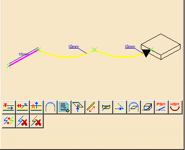
-
The current path is colored violet. A contextual menu is available:
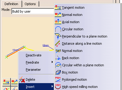
-
Deactivate: Deactivates the selected macro path,
-
Activate: Activates a path that was previously deactivated,
-
Feedrate: Allows you to modify the feedrate type associated to the selected macro path
by making a selection in the sub-menu. If Local is selected, you can assign a local feedrate value.
-
Parameter: Tunes up the parameters of the macro in the dialog box that is then displayed.

The parameters dialog box can also be launched by double-clicking a portion of the path in the viewer.

The graph displayed in the viewer of the dialog box is a generic representation of a macro mode.
It is not the true representation of the macro you are using or defining.
Click Tool Path Replay to check the result of you settings.
 -
-
When a geometry is required (e.g. Add circular within a plane motion) the geometry is also represented.
A contextual menu is available on this geometry:
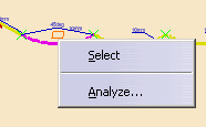
-
You can also double-click a label in the viewer.
This will start the editon dialog box of the corresponding parameter.

Numeric mode:
-
Click
 to
switch to the numeric definition mode of the macros.
-
The list of the machining modes available is displayed.
It is the same as above, with the exception of Build by user. -
When you select one mode, its sensitive icon and required parameters are displayed in the viewer:
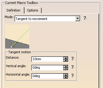
-
Set the parameters according to your needs.
Use the interrogation mark to display or hide the graphical help. -
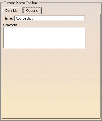
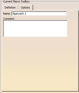
In the Options tab, you can define the name of the macro and enter a comment.
More information is available in the Macro Reference chapter.
![]()