 |
This task shows how to create a shape fillet
between two surfaces.
The fillet surface is obtained by rolling a sphere between the selected
surfaces.
This command also lets you create tritangent
shape fillets. |
| |
This task also shows you how to create
different types of variable radius fillets. |
 |
Open the
ShapeFillet1.CATPart document. |

|
-
Click Shape Fillet
 . .
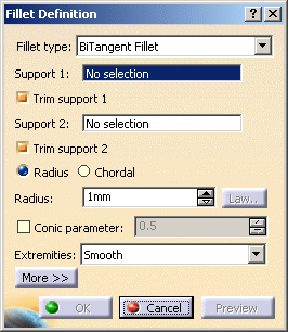
| The Fillet Definition dialog box appears. |
-
Choose the BiTangent Fillet type.
-
Select a surface as the first support element.
-
Select another surface as the second support element.
-
Enter the value of the fillet Radius.
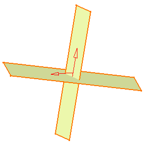
Up to four fillet locations may be possible.
To help you decide on the location an arrow is displayed on each
selected surface. You can click on the arrows to specify the desired
fillet location. |
 |
|
|
-
 |
|
-
Use the combo to choose the desired type of Extremities
for the fillet:
- Smooth: a tangency constraint is imposed at the
connection between the fillet surface and the support surfaces,
thus smoothing the connection.
- Straight: no tangency constraint is imposed at the
connecting point between the fillet and the initial supports,
generating sometimes a sharp angle.
- Maximum: the fillet surface is limited by the
longest selected support's edge.
- Minimum: the fillet surface is limited by the
shortest selected support's edge.
|
-
Click Preview to see the filleted surface:
-
Click OK to create the shape fillet.
| The surface (identified as Fillet.xxx) is added to
the specification tree. |
| |
 |
- In case the selected supports are partially tangent, it is
advisable to create an edge fillet.
- Parameters can be edited in the 3D
geometry. To have further information, refer to
Editing Parameters.
|
|
| |
Creating a Variable Radius Fillet
|
 |
With Spine and Hold Curve
|
 |
Open the
ShapeFillet3.CATPart document. |

|
You can generate a variable bi-tangent radius fillet by
selecting a Hold curve. In this case,
you need to select a previously defined limiting curve that will control
the fillet radius, and a previously defined spine that defines the planes
in which the filleted surface section will pass. Both these curves must be
larger than the surfaces involved, and the Hold curve must lie on one of
these initial surfaces. The resulting filleted surface is tangent to the
initially selected surfaces and limited by the hold curve.
|
| |
See also Creating a variable
bi-tangent circle radius fillets using a spine. |
| |
With Laws and Relimiters
|
| |
The Law button becomes
available when the Spine field is filled in. |
 |
Open the
ShapeFillet3.CATPart document. |
 |
-
Select two surfaces.
-
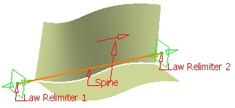
Select Line.1 as the spine.
Law relimiters are displayed on
each extremity of the spine to delimit the radius law range. Manipulators
enable you to move them along the spine.
 |
 |
You can use a close spine, in that
case, only the Law Relimiter 1 field is enabled. |
-
Click
Law... to display the Law Definition dialog box. In this case, you
need to select a law as defined in Creating
Laws.
| The 2D viewer enables you to preview the law evolution before
applying it. |
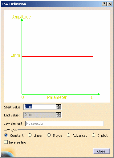 |
The Law Viewer allows you to:
- visualize the law evolution and the maximum and minimum values,
- navigate into the viewer by panning and zooming (using to the
mouse),
- trace the law coordinates by using the manipulator,
- change the viewer size by changing the panel size
- reframe on by using the viewer contextual menu
- change the law evaluation step by using the viewer contextual
menu (from 0.1 (10 evaluations) to 0.001 (1000 evaluations)).
|
 |
You can check Inverse law
to reverse the law as defined using the above options. |
-
Enter Start value and End
value.
-
Choose the type of law to be
applied to the radius.
| Five basic or advanced types are available: |
- Constant: a regular law, only one value is needed.
- Linear: a linear progression law between the
Start and End indicated values.
- S type: an S-shaped law between the two indicated
values. The pitch distance will vary between these two pitch
values.
- Advanced: allowing to select a Law element as
defined in Creating Laws.
- Implicit: allowing the selection of points on the
spine the association of values for these points.
|
a. Select points on
the spine. By default, the spine extremities (relimiters) are
selected.
b. Define a radius
for each point. For instance, set 30mm for Point.2 and 60 for
Point.3.
The radius law applies between these two points. The radius
values are interpolated into a curvature continuous radius law
defined over the whole spine curve.
c. Create a third
point between Point.2 and Point.3 with a radius of 90mm.
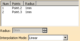
d. Define the
Interpolation Mode: Linear (straight interpolation) or
Cubic (smooth interpolation). Here we chose the Linear mode.
 |
|
-
Click Close to return to
the Fillet Definition dialog box.
-
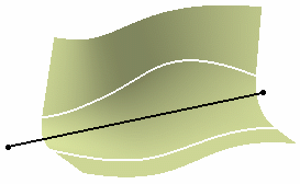
Click Preview to see the
filleted surface:
 |
 |
-
The spine curve must be
curvature continuous.
-
At least two points must
be selected on the spine.
-
If the spine is closed,
only one point is selected.
-
You can edit a point, by
right-clicking it and choosing the Edit Point contextual item.
-
You can add a point by
right-clicking and choosing the Create Point contextual item.
-
Points are automatically
reordered in the list, according to their ratio on the spine.
|
|
| |
BiTangent Fillet with Multi-ribbons
|
| |
Faces to keep lets you manage
multi-ribbons. |
 |
Open the
ShapeFillet2.CATPart document. |
 |
-
Select two surfaces.
-
Set the Radius value as 20.
-
Click Preview.
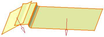 |
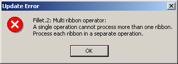
| As you selected two ribbons, an error message pops up asking you
to process each ribbon in a separate operation. |
 |
-
Click OK in the dialog
box.
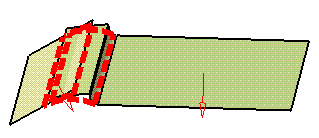
| The solutions are shown in red: |
 |
-
In the Faces to keep
field, select the face(s) you want to keep to create the shape fillet.
-
Click Preview to see the
filleted surface.
|

|
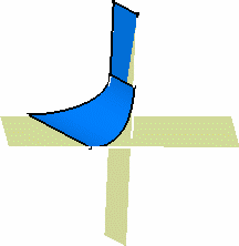
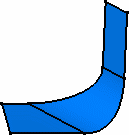
You can deselect Trim support1 and
Trim support 2. In this case, the
support element involved will not be trimmed and assembled to the filleted
surface.
By default, both options are checked, thus relimiting both support
elements.
In the examples below, we changed the filleted surface's color to better
visualize it. |
|
|
 |
| |
With only one support element trimmed: |
With both support elements trimmed: |
 |
A trim is automatically performed
when using the Generative Shape Design 1 product. |
|

|
![]()
