 |
This task shows how to create evolution laws within a .CATPart
document, to be used later on when creating Generative Shape Design
elements, such as swept surfaces, or parallel curves. |

|
Open the
Law1.CATPart document. |

|
-
Click Law
 . .
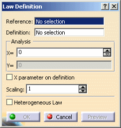
| The Law Definition dialog box appears. |
 |
-
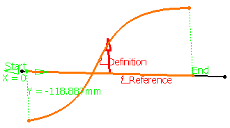
Select the reference line.
-
Select a definition curve.
| The law is computed as the distance between points on
the reference line and their matching points onto the curve. |
 |
 |
- Laws can be created using negative values.
| The intersection between the reference line and the
definition curve is taken into account to change the law
evaluation sign. |
| The direction lets allows you to choose which side of the
reference line must be considered as positive. |
- If X parameter on definition is checked, the X
parameter is displayed on the selected curve and represents the
percentage of the curvilinear abscissa on this curve. The law is
computed by projecting the start point normally onto the reference
line.
- You can analyze the law using the manipulator,
or specifying a value in the X field. This parameter represents the
percentage of the curvilinear abscissa on this curve. The law is
computed by projecting the start point normally onto the reference
line.
The Y field indicates the distance between any point on the
reference line and its matching point on the selected curve.
|
-
Define the
law amplitude by entering a value or using the graphic manipulators in
the Scaling
field.
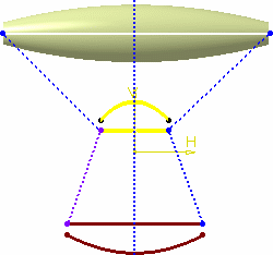
| When the law is applied to a geometric element, the latter
usually is not of the same length as the reference line. Therefore a
linear mapping is applied between the reference line and the element
the law is applied to, resulting in a scaling of the law. |
| In the illustration, the law is applied to a circular sweep (top)
and to a parallel curve (bottom). The dotted lines represent the
linear mapping between the law (middle) and the two elements to which
it is applied. |
 |
-
Check Heterogeneous Law
to define the applied law unit (none for ratio law; degree, radian, or
grade for angle law) and the distance measure units (current unit by
default).
| Two conversions will be performed during the law evaluation: |
|
|
 |
-
Click OK to create the law.
| The law (identified as Law.xxx) is added to the specification
tree. |
| It is now ready for use in the creation of other Shape Design
elements. |
-
Click Parallel Curve
 . .
-
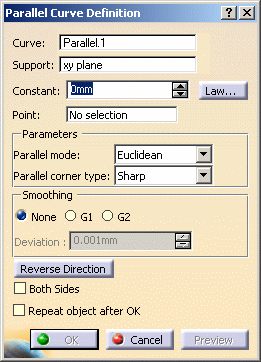
In the Parallel Curve Definition dialog box, click
Law....
-
Select the Law.1 from the specification tree.
-
Click OK.
| The law is applied to the selected element. |
 |
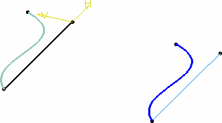 |
- When the reference line and definition curve do not present the
same length, only the common area is used to compute the law.
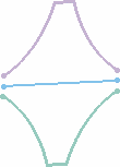
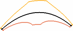
- Check Both Sides to generate a parallel curve
symmetrically on each side of the selected curve.
| Note that depending on the geometry, the
elements may not appear symmetrical. They are if the curve is a
line, otherwise, the resulting curves' shape may differ: |
 |
 |
| Resulting parallel curves when a line is selected |
Resulting parallel curves when any curve is selected |
| |
|
- When X parameter on definition is deselected, the
selected curve should not present several intersections with the
plane normal to the reference line. If there are several
intersections, the law cannot be evaluated and cannot be applied
when creating geometric elements.
|
|
 |
Laws created using the Knowledge Advisor product, being
mathematical formulas, can be used with Generative Shape Design's
operators, such as swept surfaces,
or parallel curves for
instance.
For further information, refer to
Creating and Using a Knowledge Advisor Law in Knowledge
Advisor's User's Guide.
Note that laws created using the Law icon of
Generative Shape Design product can be referenced by laws
created with Knowledge Advisor product. |
 |
Selecting a published law from another part is not
allowed. |
|

|
![]()