![]()
|
|
Sewing is a Boolean
operation combining a surface with a body. This capability adds or removes
material by modifying the surface of the solid. You can sew all types of surfaces onto bodies. Depending on your geometry, two kinds of sewing operations can be performed:
Sewing features (in boundary projection mode) is more productive (CPU cost) and more stable (geometric tangency condition) than creating a solid using the Close Surface command (when possible) because no surface/surface intersections are computed.
This task shows you both methods. |
|||||||||||||
|
|
Open the SewSurface.CATPart document. | |||||||||||||
|
|
|
|||||||||||||
Using the "Intersect body" optionYou will use the Intersect body option when the surface straightly crosses the solid without being tangent. The application then needs to compute the intersection between the surface and the solid, the portions of surface with "free edges" being eventually removed. Note that Intersect body should not be used in case of solids having Through holes or pockets and where it is not possible for surface to add material for sew operation. |
||||||||||||||
 |
||||||||||||||
| In the following example, the application can compute the intersection: | ||||||||||||||
|
|
||||||||||||||
|
|
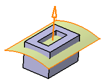
Checking
Intersect body in the Sew Surface Definition dialog
box automatically activates the Simplify geometry option. The arrow indicates the portion of material that will be kept: |
|||||||||||||
|
|
||||||||||||||
| The surface is sewn onto the body. Some material has been removed. | ||||||||||||||
|
|
||||||||||||||
|
|
If you have a Cast and Forged Part Optimizer license, you can also remove faces while sewing surfaces onto bodies. | |||||||||||||
Hybrid DesignWhen adding a surface-based feature or a surface feature modifying another surface-based feature or surface belonging to the same body, Part Design features based on that second feature then reference the new added feature. In other words, a replace operation is automatically performed. For an example, refer to Creating Splits. |
||||||||||||||
![]()