-
Select the profile to be extruded, that is Sketch.6 (located in the Part Body entity).
This open profile has been created in a plane normal to the face on which the stiffener will lie.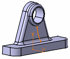
About Profiles
- You can use wireframe geometry as your profile.
- In some cases, you can define whether you need the whole profile, or sub-elements only. For more information, refer to Using the Sub-elements of a Sketch.
- Clicking the icon
 opens the Sketcher. You can then edit the profile. Once you have done
your modifications, the Stiffener Definition dialog box
reappears to let you finish your design.
 -
You can also create your profile by using any of these creation contextual commands available from the Selection field:
-
Create Sketch: launches the Sketcher after selecting any plane, and lets you sketch the profile you need as explained in the Sketcher User's Guide.
-
Create Join: joins surfaces or curves. See Joining Surfaces or Curves.
-
Create Extract: generates separate elements from non-connex sub-elements. See Extracting Geometry.
If you create any of these elements, the application then displays the corresponding icon in front of the Selection field. Clicking this icon enables you to edit the element.
-
- If you click the Selection field and select another sketch, the application immediately creates the stiffener.
- Clicking the icon
 opens the Sketcher. You can then edit the
profile to modify your stiffener. Once you have done your modifications,
you just need to quit the Sketcher. The dialog box is closed and the icon
 is activated.
 -
If you have chosen to work in a hybrid design environment, the elements created on the fly via the contextual commands mentioned above are aggregated into sketch-based features.
-
Click Stiffener
 .
.
The Stiffener Definition dialog box is displayed.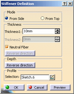
Two creation modes are available:
- From side: the extrusion is performed in the profile's plane and the thickness is added normal to the plane.
- From top: the extrusion is performed normal to the profile's plane and the thickness is added in the profile's plane.
From side is the default option. The application previews a stiffener which thickness is equal to 10mm. The extrusion will be made in three directions, two of which are opposite directions. Arrows point in these directions.
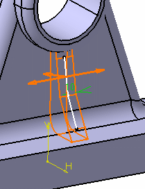
-
Uncheck the Neutral Fiber option.
The extrusion will be made in two directions only. To obtain the directions you need, you can also click the arrows. Note that you can access contextual menu items on these arrows. These commands are the same as those available in the dialog box.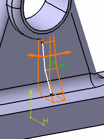
-
Check the Neutral Fiber option again.
This option adds material equally to both sides of the profile. -
Enter 12 as the thickness value.
This thickness is now evenly distributed: a thickness of 6mm is added to each side of the profile.
Optionally click Preview to see the result. -
Click OK.
The stiffener is created. The specification tree indicates it has been created.
How are Stiffeners Trimmed?
The application trims geometry in two steps: first, it trims the
different sketcher elements composing the selected profile, then
extrudes the resulting geometry and trims it to the body.
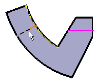
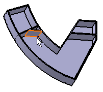
The following example shows an initial profile composed of two lines.
Because the pink line has been trimmed to the second line of the
profile, the resulting stiffener is made of three portions of material.
"From Top" Stiffeners
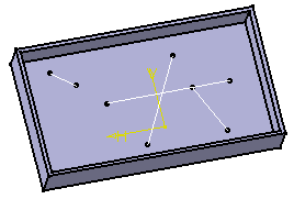
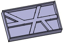
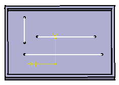
The From top option lets you create stiffeners from a network as illustrated below. You can, if you wish, create this stiffener by working on Body.2. Prior to doing so, ensure that Sketch.8 is the current object).
Figure 1: Sketch.8 includes several lines.
 |
 |
There are two ways of defining the thickness.
- The Neutral fiber option adds the same thickness to both
sides of the profile. You just need to specify the value of your choice
in Thickness 1 field and this thickness is evenly added to
each side of the profile.

- Conversely, if you wish to add different thicknesses on both sides of
the profile, just uncheck the Neutral fiber option and then
specify the value of your choice in Thickness 2 field.

 |
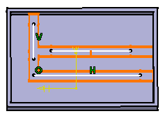
....the stiffener looks like this:
 |