The information in this section will help you create and edit 2.5 axis Groove Milling operations in your manufacturing program.
Select Groove Milling
![]() then select the
geometry to be machined
then select the
geometry to be machined
![]() .
.
Specify the tool to be used
![]() ,
NC macros
,
NC macros ![]() , and
feeds and speeds
, and
feeds and speeds ![]() as needed.
as needed.
A number of strategy parameters
![]() are available for
defining:
are available for
defining:
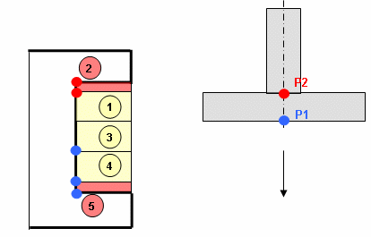
The Machining direction (Top/Bottom, Bottom/Top) and Axial strategy (Standard, Middle, Middle alternate) parameters determine the tool path ordering for machining the groove as follows:
For example, in Top/Bottom machining with Top and
Bottom finish passes, top finishing is done just after the first
machining level and just before the second machining level. |
In Bottom/top machining with Top and Bottom finish
passes, bottom finishing is done just after the first machining level
and just before the second machining level. |
| Tool path
style Indicates the cutting mode of the operation:
|
|
|
Direction of cut Specifies how machining is to be done.
|
|
| Machining
tolerance Specifies the maximum allowed distance between the theoretical and computed tool path. |
|
| Fixture
accuracy Specifies a tolerance applied to the fixture thickness. If the distance between the tool and fixture is less than fixture thickness minus fixture accuracy, the position is eliminated from the trajectory. If the distance is greater, the position is not eliminated. |
|
| Close tool
path Specifies whether or not the program must close the tool path. 
 |
|
|
Percentage overlap Specifies the amount that the tool must go beyond the end point of a closed tool path according to a percentage of the tool diameter.  |
|
|
Compensation output Allows you to manage the generation of Cutter compensation (CUTCOM) instructions. The following options are proposed:
Any user-defined PP words in macros are added to the cutter compensation instructions generated in the NC data output. Therefore you should be careful when specifying CUTCOM instructions in macros. A negative Offset on contour (parameter in Geometry tab page) is possible for 2D radial profile output.
|
|
| Compensation
on top / Compensation on bottom Specifies the tool corrector identifiers to be used in the operation. This point is switched automatically during a Return between levels macro whenever the next level to machine requires a different compensation point. The corrector type (P1, P2, P3, for example), corrector identifier and corrector number are defined on the tool. When the NC data source is generated, the corrector number can be generated using specific parameters. |
Tool follows a guiding contour between top and bottom of the groove while respecting user-defined geometry limitations and machining strategy parameters.
You can specify the following Geometry:
Guiding contours can be specified in several ways:
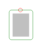
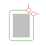
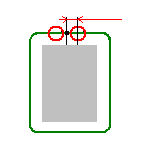
The guiding contour can be restricted by means of Start and Stop relimiting elements. The tool can be positioned In, On or Out with respect to a relimiting element. You can select a point or a curve as relimiting element.
A fast way to specify relimiting points is to right-click the guiding contour area in the sensitive icon of the dialog box and set the Relimitation point detection contextual command. When you select a guiding contour, its extremities will be used as relimiting elements.
Note that a relimiting point can be created anywhere along the guiding contour by means of the Add relimiting point contextual command. Just right-click the relimiting element area in the sensitive icon of the dialog box and select any position along the guiding contour.
Collision checking is done during macro motion. All guiding elements defined on the operation are taken into account during this verification. However, in some cases, it can be useful to deactivate collision checking with the guides (see example below).
The Collision Avoidance capability allows you to manage this collision checking.
When you select Collision checking on the Geometry tab page, the following dialog box appears.

When the Include guiding elements checkbox is selected, guides are checked for collisions during macro motion. By default the checkbox is selected.
When the checkbox is not selected, no collision verification is done with the guides during macro motions.
By default the checkbox is selected.
A Groove Milling operation uses a T-Slotter.
In the Feeds and Speeds tab page, you can specify feedrates for approach, retract, machining and finishing as well as a machining spindle speed.
Feedrates and spindle speed can be defined in linear or angular units.
A Spindle output checkbox is available for managing output of the SPINDL instruction in the generated NC data file. If the checkbox is selected, the instruction is generated. Otherwise, it is not generated.
Feeds and speeds of the operation can be updated automatically according to tooling data and the Rough or Finish quality of the operation. This is described in Update of Feeds and Speeds on Machining Operation.
You can reduce feedrates in corners encountered along the tool path depending on values given in the Feeds and Speeds tab page: reduction rate, maximum radius, minimum angle, and distances before and after the corner.
Feed reduction is applied to corners along the tool path whose radius is less than the Maximum radius value and whose arc angle is greater than the Minimum angle value. Corners can be angled or rounded.
For Groove Milling, feedrate reduction applies to inside corners for machining or finishing passes. It does not apply for macros or default linking and return motions.
If a cornering is defined with a radius of 5mm and the Feedrate reduction in corners set to a lower radius value, the feedrate will not be reduced.
You can define transition paths in your machining operations by means of NC Macros. These transition paths are useful for providing approach, retract and linking motion in the tool path.
An Approach macro is used to approach the operation start point.
A Retract macro is used to retract from the operation end point.
A Linking macro may be used in several cases, for example:
A Return on Same Level macro is used in a multi-path operation to link two consecutive paths in a given level.
A Return between Levels macro is used in a multi-level machining operation to go to the next level.
A Return to Finish Pass macro is used in a machining operation to go to the finish pass.
A Clearance macro can be used in a machining operation to avoid a fixture, for example.
Note that P2 functionalities for Groove Milling include all Finishing
parameters, and Sectioning for guiding element selection.
To edit in P1 a Groove Milling operation that was created in P2,
the following parameter values must be set: