The information in this section will help you create and edit pocketing operations in your manufacturing program.
Select Pocketing
![]() then select the geometry to be machined
then select the geometry to be machined
![]() .
.
A number of strategy parameters
![]() are available for
defining:
are available for
defining:
Specify the tool to be used
![]() ,
NC macros
,
NC macros ![]() , and
feeds and speeds
, and
feeds and speeds ![]() as needed.
as needed.
|
Finishing mode Indicates whether or not finish passes are to be generated on the sides and bottom of the area to machine. There are several possible combinations: 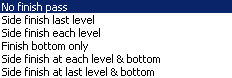 Side finishing can be done at each level or only at the last level of the operation. Bottom finishing can be done without any side finishing or with different combinations of side finishing. |
|
|
Side finish thickness Specifies the thickness of material that will be machined by the side finish pass. |
 |
|
Side thickness on bottom Specifies the thickness of material left on the side by the bottom finish pass. |
 |
|
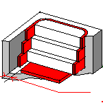
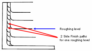
Number of side finish paths per
level Specifies the number of side finish paths for each level in a multi-level operation. This can help you reduce the number of operations in the program. |
 |
|
Bottom finish thickness Specifies the thickness of material that will be machined by the bottom finish pass. |
 |
|
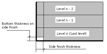
Bottom thickness on side finish Specifies the bottom thickness used for last side finish pass, if side finishing is requested on the operation.
|
|
|
Spring pass Indicates whether or not a spring pass is to be generated on the sides in the same condition as the previous Side finish pass. The spring pass is used to compensate the natural spring of the tool. |
|
|
Avoid scallops on bottom Defines whether or not the distance between paths can be adjusted by the program in order to avoid scallops on the bottom. Available for single-level and multi-level operations with bottom finish pass. |
|
|
Compensation output Allows you to manage the generation of Cutter compensation (CUTCOM) instructions for the pocketing operation's side finish pass. The following options are proposed:
Any user-defined PP words in macros are added to the cutter compensation instructions generated in the NC data output. Therefore you should be careful when specifying CUTCOM instructions in macros. A negative Offset on contour (parameter in Geometry tab page) is possible for 2D radial profile output.
|
|
|
High Speed Milling Specifies whether or not cornering for HSM is to be done on the trajectory. |
|
|
Corner radius Specifies the radius used for rounding the corners along the trajectory of a HSM operation. Value must be smaller than the tool radius. |
 |
|
Limit angle Specifies the minimum angle for rounding corners in the toolpath for a HSM operation. |
 |
|
Extra segment overlap Specifies the overlap for the extra segments that are generated for cornering in a HSM operation. This is to ensure that there is no leftover material in the corners of the trajectory. |
 |
|
Cornering on side finish path Specifies whether or not tool path cornering is to be done on side finish path. |
|
|
Corner radius on side finish path Specifies the radius used for rounding the corners of the side finish path in a HSM operation. Value must be smaller than the tool radius. |
|
|
Limit angle on side finish path Specifies the minimum angle for rounding the corners of the side finish path in a HSM operation. |
|
|
Transition radius Specifies the radius at the start and end of the transition path when moving from one path to the next in a HSM operation. |
|
|
Transition angle Specifies the angle of the transition path that allows the tool to move smoothly from one path to the next in a HSM operation. |
|
|
Transition length Specifies a minimum length for the straight segment of the transition between paths in a HSM operation. |
|
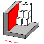
A Pocketing operation can be created for machining:
You can specify the following Geometry:
- Offset on Hard Boundary
- Offset on Soft Boundary
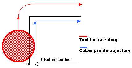
- Offset on Contour. If you specify an Offset on Contour, it is added to any defined Offset on Hard Boundary, Offset on Hard Boundary, and Offset on Island.
The pocket boundary must be closed. It can be specified in several ways:
You can select a Start point and an End point as preferential start and end positions for the operation. This allows better control for optimizing the program according to the previous and following operations.
Note that the Start point can be located outside an open pocket. In this case, you must specify a clearance with respect to the pocket boundary.
Recommended tools for pocketing are End Mills, Face Mills and T-Slotters.
In the Feeds and Speeds tab page, you can specify feedrates for approach, retract, machining and finishing as well as a machining spindle speed.
Feedrates and spindle speed can be defined in linear or angular units.
A Spindle output checkbox is available for managing output of the SPINDL instruction in the generated NC data file. If the checkbox is selected, the instruction is generated. Otherwise, it is not generated.
Feeds and speeds of the operation can be updated automatically according to tooling data and the Rough or Finish quality of the operation. This is described in Update of Feeds and Speeds on Machining Operation.
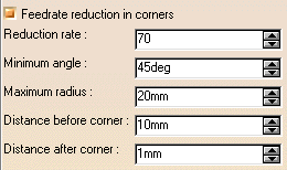
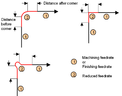
You can reduce feedrates in corners encountered along the tool path depending on values given in the Feeds and Speeds tab page: reduction rate, maximum radius, minimum angle, and distances before and after the corner.
Feed reduction is applied to corners along the tool path whose radius is less than the Maximum radius value and whose arc angle is greater than the Minimum angle value.
For Pocketing, feedrate reduction applies to machining and finishing passes:
Feedrate reduction does not apply for macros or default linking and return motions.
Corners can be angled or rounded, and may include extra segments for HSM operations.
You can use Slowdown rate in the Feeds and Speeds tab page to reduce the current feedrate by a given percentage.
The reduction is applied to the first channel cut and to the transitions between passes.
If a corner is included in a Slowdown path, the general rule is that the lowest percentage value is taken into account.
For example, if the Slowdown rate is set to 70 % and Feedrate reduction rate
in corners is set to 50%, the feedrate sequence is:
100%, 70% (entry in slowdown), 50% (entry in corner), 70% (end of corner, still
in slowdown), 100% (end of slowdown).
If Feedrate reduction rate in corners is then set to 75%, the feedrate
sequence is:
100%, 70% (entry in slowdown), 70% (entry in corner: 75% ignored), 70%
(end of corner, still in slowdown), 100% (end of slowdown).
You can define transition paths in your machining operations by means of NC Macros. These transition paths are useful for providing approach, retract and linking motion in the tool path.
An Approach macro is used to approach the operation start point.
A Retract macro is used to retract from the operation end point.
A Linking macro may be used, for example:
A Return on Same Level macro is used in a multi-path operation to link two consecutive paths in a given level.
A Return between Levels macro is used in a multi-level machining operation to go to the next level.
A Return to Finish Pass macro is used in a machining operation to go to the finish pass.
A Clearance macro can be used in a machining operation to avoid a fixture, for example.
Note: When a collision is detected between the tool and the part or a check element, a clearance macro is applied automatically. If applying a clearance macro would also result in a collision, then a linking macro is applied. In this case, the top plane defined in the operation is used in the linking macro.
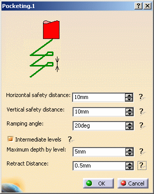
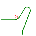
When specifying a Ramping Approach macro in Pocketing, you can select the Parameter contextual command to access the parameters of the macro path.
If you select the Intermediate Levels checkbox, the approach macro is divided into three parts:
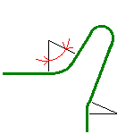
The yellow path in the figure below illustrates an intermediate level for a ramping approach macro in Back and Forth mode.
Note that P2 functionalities for Pocketing include Automatic Draft
Angle, all Finishing parameters, and Sectioning for guiding element selection.
To edit in P1 a Pocketing operation that was created in P2, the
following parameter values must be set:
 or
Conventional milling
or
Conventional milling
 or Stepover
ratio
or Stepover
ratio 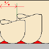 .
. 
 Avoid scallops:
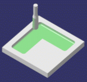
 Truncated: