|
|
This task shows how to insert a
Thread Milling operation in the program. For this operation,
machining is done in one or more helical passes. To create the
operation you must define:
|
||
|
|
Open the
HoleMakingOperations.CATPart document, then select the desired
Machining workbench from the Start menu. Make the
Manufacturing Program current in the specification tree. |
||
|
|
1. |
Select
Thread Milling
A Thread Milling entity along with a default tool is added to the program. The Thread Milling dialog box appears directly at the
Geometry tab page
|
 |
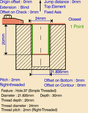
| 2. | Select the red
hole depth representation then select a threaded hole feature in the 3D
window. Just double click to end your selection. The sensitive icon is updated with the following:
You can modify this data. |
||
| 3. | If needed, enter offset values for the Bottom and Contour. | ||
| 4. | If needed, you can invert the tool axis direction by selecting the axis representation in the sensitive icon. | ||
| 5. |
Select the Strategy tab
page
Note that the figure displaying the toolpath in this page is different according the Machining strategy and Machining direction settings. Also note that Breakthrough is not available when the Extension type in the Geometry tab page is set to Blind. |
 |
|
|
|
A tool is proposed by default when you want
to create a machining operation. If the proposed tool is not suitable,
just select the Tool tab page
Thread mills or boring bars can be used in this type of operation. If you use a boring bar, machining can be done in Mono-pass mode only. If you use a thread mill in Optimized passes mode, the number of helical toolpaths depends on the effective thread length of the tool and the thread depth of the hole. Refer to Edit the Tool of an Operation for more information. |
||
| 6. | Select the
Feeds and Speeds tab page
Note that in the toolpath represented in the strategy page shown above, tool motion is at:
|
||
| 7. | Select the
Macros tab page
|
||
|
|
Before accepting the operation, you should check its validity by replaying the tool path. | ||
| 8. | Click OK to create the operation. | ||
|
|
Example of
output If your PP table is customized with the following statement for Thread Milling operations:
A typical NC data output is as follows:
Note that the helical toolpath is generated with GOTO statements. You can use Edit Cycle
The parameters available for PP word syntaxes for this type of operation are described in the NC_THREAD_MILLING section of the Manufacturing Infrastructure User's Guide. |
||
|
|
|||