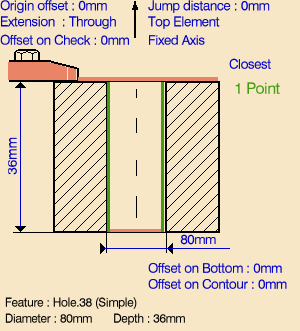
- the geometry of the holes to be machined

- the tool that will be used

- the parameters of the machining strategy

Machining workbench from the
Start menu.
Make the Manufacturing Program current in the specification tree.
A Circular Milling entity along with a default tool is added to the program.
The Circular Milling dialog box appears directly at the
Geometry tab page
![]() .
.

Just double click to end your selections.
- Standard
- Helical.

- Approach clearance
- Machining tolerance
- Direction of cut
- Percentage overlap
- Compensation number depending on those available on the tool
- Breakthrough
- Number of paths and Distance between paths
- Axial mode: Maximum depth of cut or Number of levels (with or without top)
- Sequencing mode: Axial first or Radial first
- Automatic draft angle.
- Breakthrough
- Helix mode: By angle or By pitch
- Angle or Pitch value.
If the proposed tool
is not suitable, just select the Tool tab page
![]() to specify the
tool you want to use. This is described in
Edit the Tool of an Operation.
to specify the
tool you want to use. This is described in
Edit the Tool of an Operation.
Note that in the toolpath represented in the strategy page, tool motion is at:
- Motion at machining feedrate from 1 to 2
- Motion at feedrates defined on macros from 2 to 3, 3 to 4, 4 to 2', 2' to 3' and 3' to 4'
- Retract at retract feedrate from 4' to 5.
If your PP table is customized with the following statement for Circular Milling operations:
     CYCLE/CIRCULARMILLING, %MFG_TOTAL_DEPTH, %MFG_FEED_MACH_VALUE,
     &MFG_FEED_UNIT, %MFG_CLEAR_TIP
A typical NC data output is as follows:
     CYCLE/CIRCULARMILLING, 38.500000, 500.000000,
     MMPM, 2.500000
You can use Edit Cycle
![]() to edit or
choose output syntaxes. For more information please refer to
Editing Cycle Syntaxes in Axial
Machining Operations.
to edit or
choose output syntaxes. For more information please refer to
Editing Cycle Syntaxes in Axial
Machining Operations.
The parameters available for PP word syntaxes for this type of operation are described in the NC_CIRCULAR_MILLING section of the Manufacturing Infrastructure User's Guide.
![]()