|
|
This task shows how to insert a 'Between Two Planes'
Profile Contouring operation
in the program. To create the operation you must define:
|
|
|
|
Open the PrismaticMilling01.CATPart
document, then select the desired Machining
workbench from the Start menu. Make
the Manufacturing Program current in the specification tree.
|
|
|
|
1. |
Select Profile Contouring
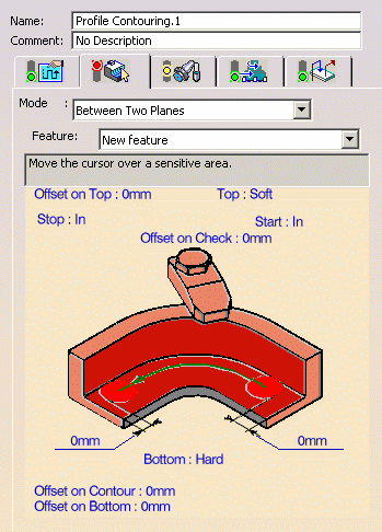
Set the Contouring mode to Between Two Planes.
|
|
|
The part bottom and flanks in the icon are colored red indicating that this geometry is required for defining the operation. All other geometry is optional. | |
| 2. | Click the red bottom in the icon, then select the underside of the part in the 3D window. | |
| 3. | Set the Bottom type to Soft by clicking the text, then set the Offset on Bottom to -5mm. | |
| 4. | Click the red flank in the icon, then select the profile along the front edge of the part in the 3D window. | |
| 5. |
Right click Start to set this condition to Out. Click the first relimiting element in the icon, then select the horizontal edge at one end of the contour profile in the 3D window. |
|
| 6. |
Right click Stop to set this condition to Out. Click the second relimiting element in the icon, then select the horizontal edge at the other end of the contour profile in the 3D window. |
|
| 7. | Click the check element in the icon, then select the top face of the green fixture in the 3D window. | |
|
|
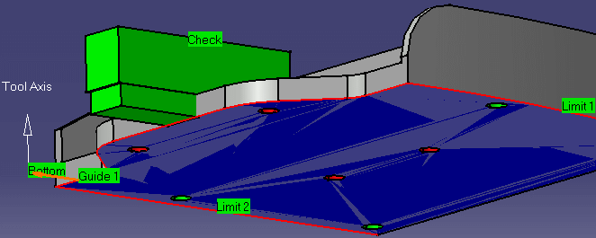
The bottom, guide, limit and check elements of the icon are now colored green indicating that this geometry is now defined. These are also indicated on the part. | |
|
|
||
| 8. |
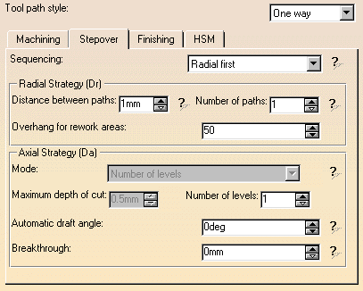
Select the Strategy tab page
|
|
|
|
Output type in the Machining tab allows you to manage the generation of Cutter compensation (CUTCOM) instructions in the NC data output. See Reference section for more information. | |
| 9. |
A tool is proposed by default when you want to create a
machining operation. If the proposed tool is not suitable,
just select the Tool tab page
This is described in Edit the Tool of an Operation. |
|
| 10. |
Select the Feeds and Speeds tab
page
|
|
| 11. |
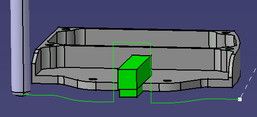
Check the validity of the operation by
replaying the tool path.
|
|
|
|
The specified operation uses a default linking macro to
avoid collision with the selected fixture. You can optimize
the linking macro and add approach and retract macros to
the operation in the Macros tab page
Please note that if a user-defined linking macro is not collision free, a default linking macro is applied. For more information please refer to Define Macros of a Milling Operation. |
|
| 12. | Click OK to create the operation. | |
More About Profile Contouring Operations
|
||
|
|
||


