- Defining the Fixed Part
- Defining the Prismatic Joints
- Defining the Revolute Joint

Defining Rigid Joints is described in separate procedure, because it uses different sample data.
Defining a Fixed Part
-
From the Machine Building tool bar, click Fixed Part
 or select Insert > Fixed Part from the menu bar.
 The New Fixed Part dialog box is displayed. 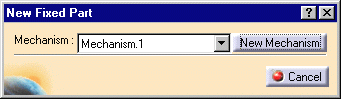
-
Select the Base (Base.1) product from the specification tree or from the geometry area.
The fix part appears in the specification tree under the Mechanisms node. 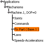
Defining the Prismatic Joints
-
On the Machine Building toolbar, click Prismatic Joint
 .
.
The Joint Creation Prismatic dialog box appears. 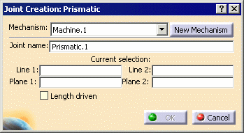
-
In the Joint Name field, enter YAxis.
-
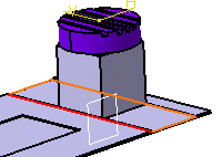
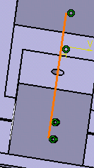
Select the bottom edge on the Base part for Line 1.

Because the parts need to be selected in this order, click Hide/Show  enable you to select the relevant geometry.
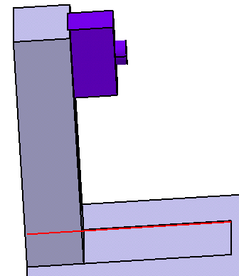
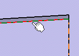
Select the bottom edge on the YAxis part for Line 2. 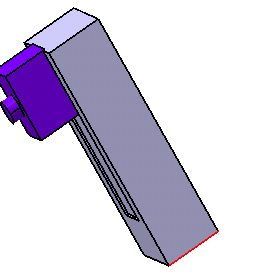
-
Select the bottom edge on the Base part for Plane 1.
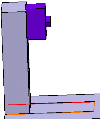
Select the bottom edge on the YAxis part for Plane 2. 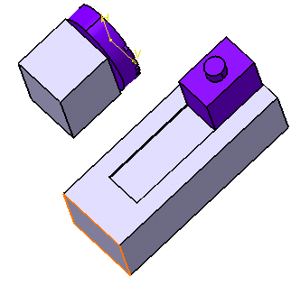
-
Select the Length driven check box; click OK.
An Information message appears. 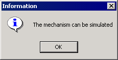
-
Click OK.
-
Repeat Steps 3-7 to define a prismatic joint between the YAxis and ZAxis parts; name the joint ZAxis.
-
Repeat Steps 3-6 to define a prismatic joint between the Base and XAxis parts; name the joint XAxis.
Currently, the machine kinematics are complete for a 3-axis machine. Defining a Revolute Joint
-
On the Machine Building toolbar, click Revolute Joint
 .
.The Joint Creation Revolute dialog box appears. 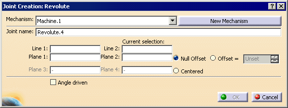
-
In the Joint Name field, enter CAxis.
-
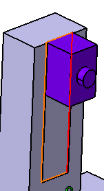
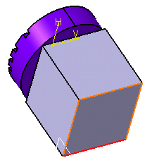
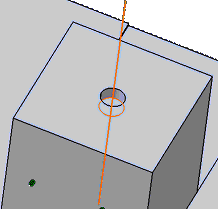
Select the axis of the hole on the XAxis part for Line 1.
Select the axis on the CTable part for Line 2. 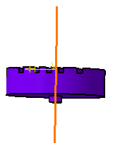
-
Select the bottom plane of the hole at the top of the XAxis part for Plane 1.
Select the bottom plane on the cylindrical protrusion on the CTable part for Plane 2. 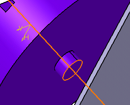
-
Select the Angle driven check box; click OK on the Joint Creation Revolute dialog box.
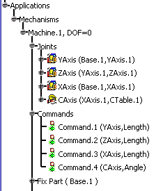
You have defined all the joints of the machine. The specification tree corresponding to the mechanism node appears as shown below.