 |
This task describes how to define a rigid joint between
the Shaft part and the CTable_Rigid part. Once this
revolute joint is defined, the table rotates with the Shaft
part. |
 |
Open the
V4Axis_Machine_With_Rigid_Joint.CATProduct file from the online/mtbug_C2/samples/V5/4Axis
Machine
directory. Because other procedures have descriptions of how to
create new machines, and define fixed parts, these steps do not need to be
done on this data, although these operations need to be performed when you
define a rigid joint for your own data. |
 |
-
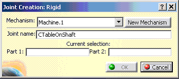
On the Machine Building toolbar, click Rigid Joint  . .
| The Joint Creation Rigid dialog box appears. |
 |
-
In the Joint Name field, enter
CTableOnShaft.
-
From the specification tree, select Shaft part
for Part 1 and select CTable_Rigid to define
Part 2
-
Click OK.
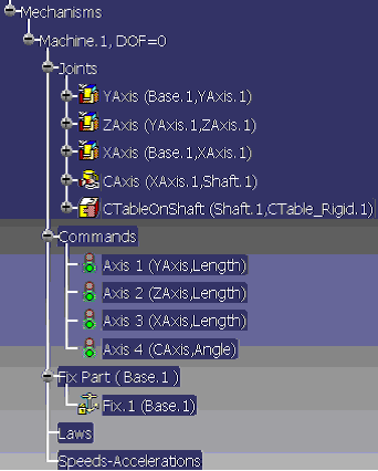
| The machine kinematics definition for a four axis machine is now
complete. The table is fixed to a rotating shaft by means of a
rigid joint; the specification tree appears below. |
 |
|
 .
.
