![]()
Select the General tab, which is divided up into areas.
Parameters in this area... Allow you to customize... Performance settings for optimized performance Tree Display display of the specification tree Color and Highlight colors of displayed geometry and parameters Tool Path Replay tool display during tool path replay Complementary Geometry handling of geometry necessary for manufacturing Design Changes use of the Smart NC mode and enhanced detection of design changes.
Performance
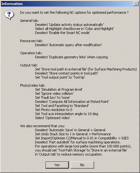
Click the Optimize button in order to automatically set a number of the Machining options for optimized performance. These options are listed in the Information dialog box that appears:

If you click Yes, these options will be set as
described in the dialog box. Note that, if needed, you may locally reset
any of these options.
If you click No, the options will remain with their current
settings.
The Information box also lists some recommendations for manually setting other options that have an influence on performance.
Tree Display
- Select the check box if you want the status of activities in the tree to be updated automatically.
- If this check box is not selected, you can display the status of one
or more selected activities in the tree using Display Status of
Selected Activities
 in the Auxiliary
Commands toolbar.
If this check box is not selected, performance is improved.
![]() By default, the check box is not selected.
By default, the check box is not selected.
Color and Highlight

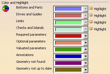
- Select the colors to be used for identifying the various
manufacturing entities by means of the combos.
Note that for Geometry that is not found or not up to date, you can select the colors used to display the valuated parameters in the corresponding Operation or Feature dialog boxes. - For certain entities, you can select the corresponding check box to
use highlighting.
Performance is improved when all the Highlight check boxes are selected.
Tool Path Replay

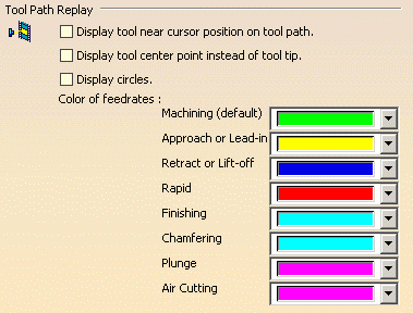
Display tool near cursor position on tool path
Select this check box if you want to display the tool near your cursor position on the trajectory during a tool path replay.
You can display the tool at a specific
point by clicking on the tool path. The tool will then be positioned on the
nearest computed point on the trajectory. To remove the tool from that
position, just click anywhere on the tool or tool path.
Please note that, as from Release 15, this positioning capability is
available even when the check box is not selected.
Display tool center instead of tool tip
Select this check box if you want to display the tool center point instead of the tool tip during a tool path replay.
Display circles
Select this check box if you want to display each circular trajectory as
a circular arc instead of a set of discretization points. The extremities
of the circular arc are indicated by means of 'O' symbols.
This allows better control of the Point by Point replay mode, where it is
necessary to make several interactions to replay a circle (because of its
representation by a set of points). With the graphic representation as a
circle, only one interaction is necessary to perform the replay.
![]() By default, these check boxes are not selected.
By default, these check boxes are not selected.
Color of feedrates
Select the colors to be used for identifying the various feedrate types by means of the combos. The selected colors will be displayed in the Different colors replay mode.
Note: The default feedrate
color in the Same color replay mode is Green.
However for the Multi-Slide Lathe Machining product, this default color
in the Same color replay mode depends on the Machining Operation.
It will be the same as the color of Lines and Curves set in the
Machining Operation properties Graphic tab page. By default, the colors
for the various Turning operations are as follows:
Yellow: Rough Turning
Blue: Groove Turning
Orange: Profile Finish Turning
Dark Green: Groove Finish Turning
Light Grey: Recess Turning
Purple Blue: Sequential Turning
Purple: Thread Turning
Red: Ramp Rough Turning
Bright Blue: Ramp Recess Turning.
Complementary Geometry
Select the check box to create a CATPart dedicated to manufacturing-specific geometry in the Product List of the PPR tree.
![]() By default, the check box is not selected.
By default, the check box is not selected.
Design Changes

Smart NC mode
Select this check box to activate the Smart NC mode. In this mode, an
image of the geometry selected in machining operations is kept to allow
analysis of design changes.
Performance is improved when this check box is not selected.
Optimized detection of design changes
Select this check box to enable a geometrical comparison mode for
detecting design changes.
This mode determines with more precision the design change status of
machining operations when a product is replaced in the Part Operation
(using either the Part Operation editor or the Edit Links capability). This
option has no effect on all other design change methods such as direct
modification in the Part.
![]() By default, these check boxes are not selected.
By default, these check boxes are not selected.