Note: Version 5 does not manage Version 4 layers on which dittos are located.
If you want to know how to apply, create, modify and delete layer filters on a CATIA Version 4 model, in CATIA V5, please refer to Managing Layer Filters on CATIA V4 models.
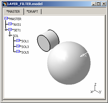
Copying/pasting the V4 layer filter entity into CATIA V5
 |
-
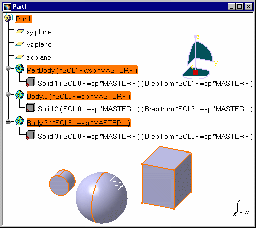
Apply a Check As Result on the V4 solid: All the primitives can be transferred into CATIA V5.
-
Copy / Paste AS RESULT the model into a CATIA V5 CATPart.
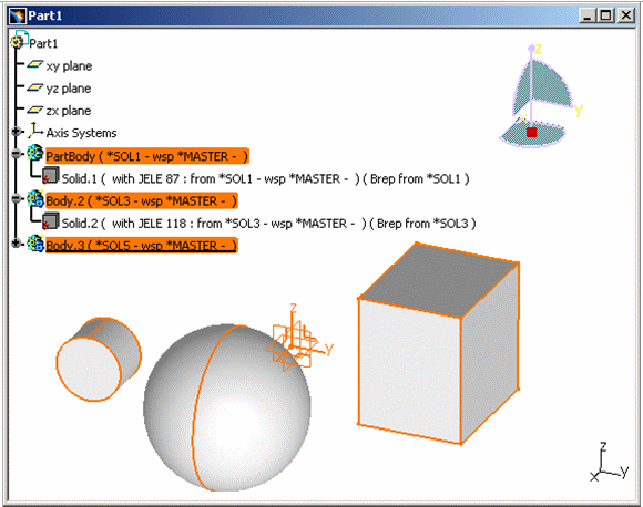
Then update the new CATIA V5 document:
The solid elements have been correctly migrated, their geometry is visible in V5 and the object (cube) is displayed. In CATIA V4, this object was assigned to Layer 2 and it was filtered. By default, during the migration, all the layers are taken into account and, therefore no filter is applied.
-
Select the View > Toolbars > Graphic Properties command...

... to look at the Graphic Properties toolbar:
-
Click the drop down arrow on the Layer icon box in order to see the layers' name or number:
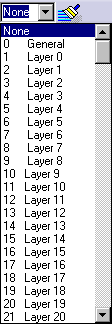
-
Select the root object Part1 in the tree, click the Layer box and you will see the layer number:
 . The root object is assigned to
the layer number "0".
Select Body.3 (*SOL5 - wsp *MASTER -) in the tree, click the arrow on the Layer box and the layer number appears in the Layer box:
.
Select PartBody (*SOL1 - wsp *MASTER -) in the tree, click the arrow on the Layer box and the layer number appears in the Layer box:
.
Select Body.2 (*SOL3 - wsp *MASTER -) in the tree, click the arrow on the Layer box and the layer number appears in the Layer box:
.
-
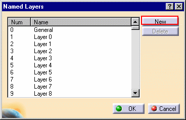
If you want to create a new layer, select the 0ther Layers... command from the list:
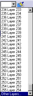
The Layer box also contains the "Other Layers..." command which lets you create your own named layers. Refer to "Creating New Layers" in CATIA - Infrastructure User's Guide for more details.
Click New in the Named Layers dialog box:
If you want to rename a layer when creating it, after clicking the New button, slowly click twice the line containing the layer name to make the field editable. This enables you to set up named layers to comply with your company's layer conventions.
-
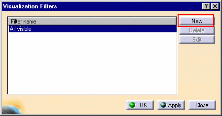
You then create filters to visualize (or not) only those objects located on the layers in the filter. In order to use visualization filters, select Tools > Visualization Filters... command:
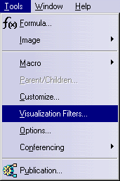
The following dialog box appears:
The default current filter "All visible" is applied automatically (filters are not transferred during the V4 to V5 Migration): it lets you see all the contents of the document. This filter cannot be deleted.
-
You can create filters by clicking the NEW button and the following dialog box is displayed:
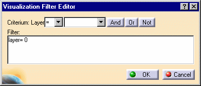
-
Click in the Filter field, delete "0" then type "2" so that the filter syntax now looks like this: layer=2, which corresponds to the cube's layer number. In the Criterium: Layer field, select the comparison operator "!=" so that the cube object may be filtered and only the cylinder and the sphere will appear in the geometry space.
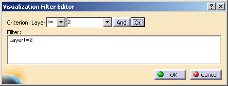
-
Select PartBody (*SOL1 - wsp *MASTER -) in the tree and click OK in the Visualization Filter Editor dialog box. In the Visualization Filters dialog box: this creates a new filter "Filter001" (with the default filter syntax) on the Cube object:
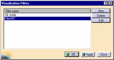
-
Select Filter001 in the Visualization Filters dialog box and click OK. The cube object is no longer displayed, and the filter remains active.
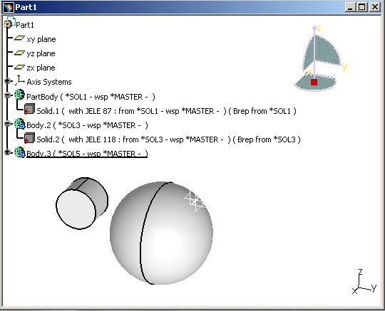
To see all the objects again, select the "All visible" filter in the Visualization Filters dialog box, then click OK.
-
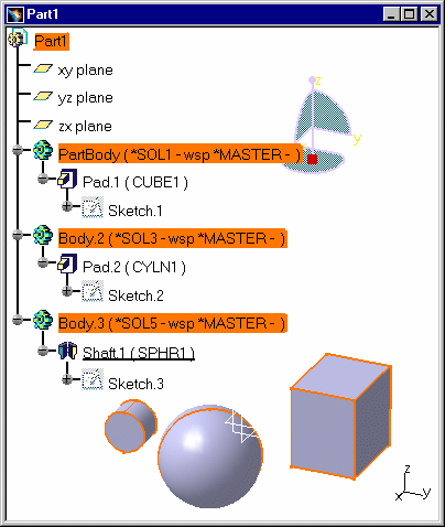
Copy / Paste AS SPEC the .model document into a V5 CATPart...
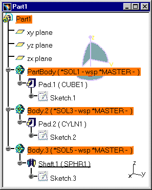
Then update the new CATIA V5 document:
All the elements of the model are migrated and you have access to the model's geometry and specifications. Therefore, you can now modify each feature of the V5 CATPart document.
Migrating V4 layer filters into CATIA V5 with the V4 To V5 Migration Batch
It is possible to migrate layers and layer filters through the Migration Batch.
After the migration, you can have access to the filter in the resulting CATPart. For this, you need to select Tools>Visualization Filters, and the Visualization Filters window appears: the list of the filters is available.
Then, you can select a filter and click the Apply button to apply the filter to the document.
You can also select a filter and click the Edit button to modify the filter's characteristics.
V4 to V5 Migration
As Result As Spec SPACE Elements Infrastructure - Structural Entities Model CATProduct, CATPart and/or CATDrawing Session CATProduct Library (SPACE Detail) Catalogs of Parts Assembly Files CATProduct & Assembly Constraints Detail used for Ditto In the interactive mode, with the copy / paste AS RESULT of Dittos, the elements of the linked Detail are copied AS RESULT, updated, and put into the No Show space. In the Batch Mode, the elements of the linked Detail are copied AS RESULT.
In the interactive mode, with the copy / paste AS SPEC of Dittos, the elements of the linked Detail are copied AS SPEC, updated, and put in the No Show space. In the Batch Mode, you get a V5 Part or a Product.
Ditto In the interactive mode, the Dittos are represented in the Part by a link on the bodies managed by the copy AS RESULT operation of the Detail elements. In the Batch Mode, the Dittos are represented in the Part by a link on the bodies managed by the copy AS RESULT operation of the Detail elements.
In the interactive mode, the Dittos are represented in the Part by a link on the bodies managed by the Copy AS SPEC of the Detail elements. In the Batch Mode, you get a V5 Part or a Product.
Detail for Macro-Primitives N/A In the interactive mode, for the copy / paste AS SPEC of a solid using Macro-Primitives, the elements of the linked Detail are copied AS SPEC, updated, and put in the No Show space. Macro-Primitives In the interactive mode, the solid who contains the Macro-Primitive is copied AS RESULT: it means that only its BRep is copied, without specifications. In the interactive mode, the Macro-Primitives are represented within the specifications tree of the body by links with the copy AS SPEC of the Detail elements. Layers The layer's numbers are transferred but not the filters. The layer's numbers are transferred but not the filters. Geometric sets You get a V5 Part. All the elements of the Set are migrated. You get a V5 Part. All the elements of the Set are migrated. Transformation N/A Affects Specifications Show/No Show The Show / No Show characteristic is respected.
Dittos (*DIT) in No Show are not migrated.
Macro-Primitives in No Show are not migrated.The Show / No Show characteristic is respected.
Dittos (*DIT) in No Show are not migrated.
Macro-Primitives in No Show are not migrated.Color Tables Color Tables Display Types (graphic) N/A Models Naming V5 document Names Models Comments Product Description Property Tolerances N/A
![]()
