This task shows how to add/remove constraints as mesh specifications either using the geometry (curves or point) or directly on the geometrical simplification (edges or vertices).
Adding/Removing Constraints (Specifications):
Two types of constraints exist:
- a constraint applied to a vertex/point: as a result, a node will be created on this vertex.
- a constraint applied to a edge/curve: as a result, all the element edges will be aligned on this curve.
On/From The Geometrical Simplification
Open the sample05.CATAnalysis document from the samples directory.
-
Enter the Advanced Surface Mesher workshop.
For more details, refer to Entering the Advanced Surface Mesher Workshop.
-
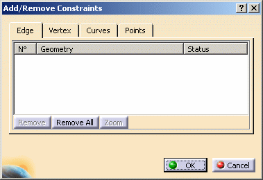
Click Add/Remove Constraints
 in the Local Specifications toolbar.
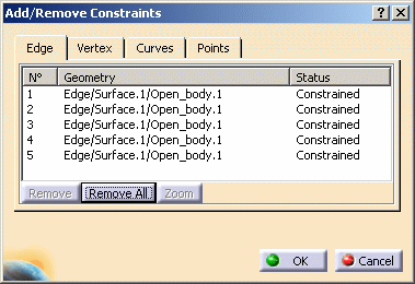
The Add/Remove Constraints dialog box appears with tabs that will allow you assigning constraints to edges, vertices / curves, points.

The last selected tab in which you performed a modification and a validation using the OK button is saved in settings.
That means that this tab will be displayed the next time you launch the Add/Remove Constraints functionality.The Trap Type dialog box also appears and remains displayed as long as you keep the Edge tab active:

You can use multi-selection:
- using an intersection polygon trap: all the domains which have non-empty intersection with the trap will be selected.
- using an inclusive polygon trap: all the domains that are completely included within the trap will be selected.
-
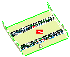
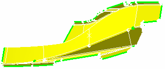
Select the edge which you want to constrain.
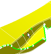
Note that you can use edge selection by path.
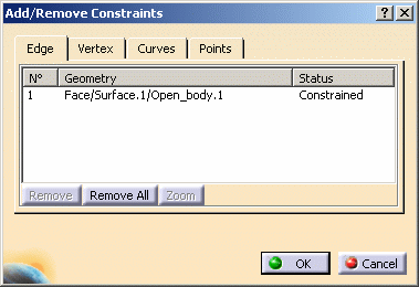
The Add/Remove Constraints dialog box now displays information on the element just selected.
-
Select the vertex which you want to constrain.
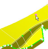
The dialog box now displays information on the element just selected.
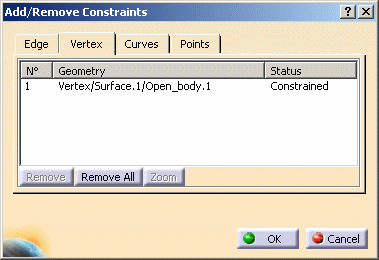
If you select one element in this dialog box buttons become selectable:
- Remove: you can remove one constraint you previously created using this dialog box.
- Remove All: you can remove all the constraints you previously created using this dialog box.
- Zoom: you can zoom in on the constraint that is currently selected in this dialog box.
-
Click OK.
On/From The Geometry
Open the sample17.CATAnalysis document from the samples directory.
-
Enter the Advanced Surface Mesher workshop.
For more details, refer to Entering the Advanced Surface Mesher Workshop.
-
Select Add/Remove Constraints
in the Local Specifications toolbar.The Add/Remove Constraints dialog box appears with tabs that will allow you assigning constraints to edges, vertices, curves and points.
-
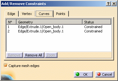
Select the Curve tab in the Add/Remove Constraints dialog box and the desired geometry on the CATAnalysis document.
Note that you can select the mono-dimension feature of a face or an edge. When selecting a face, the edges of the face are projected. For mono-dimension features (for example, intersection features), all the edges of the feature are projected.
The Add/Remove Constraints dialog box now displays information on the elements just selected as well as the possibility to Capture Mesh edges from one curve to another.
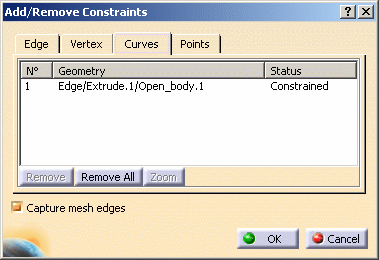
Note that you can use external curve selection by path.
-
Select more curves on the geometry.
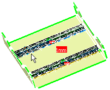
The dialog box is now as shown here:
The Capture dialog box appears to let you select the destination curve edge and, if needed, (Show Sources button) a source curve edge. In other words, you will select both edges one after the other.
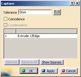
- Tolerance: mesh will be found automatically relatively to the selected tolerance.
- Coincidence: you can decide that you will have the nodes from both edges superimposed (nodes created in coincidence)
- Condensation: you can decide that the nodes from both edges (receiver and source) are single nodes. The nodes of the source will be taken into account.
- Receivers: the edge on which the source will be projected.
- Show Sources: a switch that lets you select the curve to be projected onto the receiver.
-
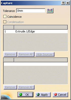
Click Show Sources in the Capture dialog box.
You can now select the curve to be projected onto the receiver.
-
Click OK in the Capture dialog box.
-
Click OK in the Add/Remove Constraints dialog box.
-
Mesh the surface.
To do this: -
Click Mesh The Part
 in the Execution toolbar.
 -
Click OK in the Mesh The part dialog box.
The part is meshed.
-
Using Edge/External Curve Selection by Path
Open the sample05.CATAnalysis document from the samples directory.
-
Enter the Advanced Surface Mesher workshop.
For more details, refer to Entering the Advanced Surface Mesher Workshop.
-
Click Add/Remove Constraints
in the Local Specifications toolbar.The Add/Remove Constraints dialog box appears.
-
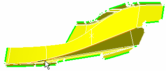
Go over an edge with the cursor.
-
Press the Shift key.
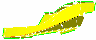
The path corresponding to the edge you went over with the cursor is highlighted.
-
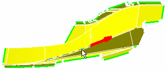
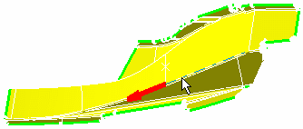
Choose the direction of the path by positioning the cursor on the path accordingly.
-
When you are satisfied with the operation, click on the path at the very point where you want the edge path to end.
The edge path is defined.
The Add/Remove Constraints dialog box is updated:
|
|
Only updated mesh parts will be constrained. In others words, when you constrain the edge of a part, if you modify the associated geometry (external edges), you need to force an update on this part to have this part up to date. |