
|
The Join feature is a
multi-body functional feature which connects
two bodies with screws as the joining elements. Within each of the joined
bodies, the necessary shapes to accommodate the screws are created. For
each body that is being connected, the Join command will create a Join
feature. In the two body case, two Join features (representing a Join head
and a Join thread) will be created: one for each connected body (similar to
the Lip feature). During the Join definition,
it is not necessary to specify both of these bodies. However once the Join
has been defined, it is not possible to change the bodies that the features
were placed in.
One of the Join features is created in the active
body. When this body is one half of a divided body that is in the document,
then both the Join head and the Join thread features are created
automatically. When instead the other half of the divided body is
missing (either deleted or not created) or the active body is not the
result of a division, then only the join head or thread is created. During
the initial creation of the Join features, different non-active bodies may
be specified as the body to connect the active one to.
Similarly to the Lip
feature each of the two individual Join features has a separate life cycle.
Therefore it is possible to delete the Join feature from each joined body
separately.
This task shows you how to use the Join command to create
Join features on associated bodies that were created by the same
Divide. |

|
Open the
Join.CATPart document. |

|
-
Click the Join
icon  . .
The Join dialog box is displayed.
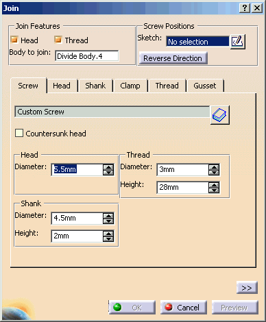 By
default during the creation of the Join, the Head and Thread buttons
are selected. If the active body (in this case, Divide Body.3)
is the result of a Divide and its associated non-active body (Divide
Body.4) is present, the associated body is automatically
selected as the entry in the Body to join field. Otherwise
this field is blank.
During the Join creation, this field can be cleared by clicking
Head or Thread to deselect them. In this case,
the Join feature will be a Head or Thread depending on which button
is set; the associated Join Feature cannot be created afterwards.
By selecting both Head and Thread options, the Body to join field is
re-activated. And you may need to select a body in the Body to join
field.
Once you click OK, neither the Body to join
field nor the Head and Thread options can be
changed when editing them. When the Join is edited, the Body to
join field will display the name of the associated body
in gray color. |
-
Select the point in the center of the plane (Sketch.2) as
the Sketch for the Screw Positions.
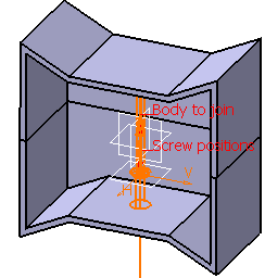
At each non-construction point defined in
the sketch, a screw will be positioned. The tip of the arrow points
to the body that will be the Thread.
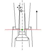 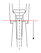
In this case, the lower body will have the Head geometry
constructed within it. While the upper body will have the Thread
geometry. By either clicking on the arrow or clicking on the
Reverse Direction button, the tip of the arrow will be reversed,
and therefore the geometries will be the opposite from what was
described (i.e. the lower body contains the Thread geometry while the
upper body contains the Head geometry). |
-
In the Screw tab, check Countersunk head.
Define the parameters as
shown below:
-
In the Head tab, the parameters as shown
below:
-
In the Shank tab, the parameters as shown
below:
-
In the Clamp tab, the parameters as shown below:
-
In the Thread tab, the parameters as shown
below:
-
Now that the desired Join feature has been defined, click
OK to create the feature.
In order to see better geometry view you just created,
we will use the Divide feature to split the
upper and lower bodies. The upper body is currently the active one so the
Divide will modify it.
Click the Divide icon
 . .
The Divide
dialog box is displayed. The in-work body is detected: Divide Body.3
is to be divided. Select the YZ Plane as the dividing element.
Uncheck Keep both sides checkbox. And then
click the Reverse Direction button. Click OK. -
The lower body needs to be divided. Since the
Divide feature works on the active body, it
is necessary to make the lower body the active one by selecting
Define in Work Object.
Click the Divide icon
 . .
The Divide
dialog box is displayed. The in-work body is detected: Divide Body.4
is to be divided. Select the YZ Plane as the dividing element.
Unselect Keep both sides checkbox. And then
click the Reverse Direction button.
Click OK.
|
|
|
You can create a Join feature externally outside of the
joining bodies. For the outside joins the Guide height should be set to 0.0. If
the Guide height is not set to 0.0, the Guide will be added to the inside
geometry but not the outside geometry. If Gussets are activated, they
also only create inside geometry.
|
|
|
You can define gussets around the Head and the Thread of a join feature. A join feature often has stiffening gussets around the head, thread or both.
|

|
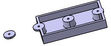
Open the
Join_Gusset.CATPart document.
 |

|
-
Click Join.1 under Divide Body.2 in the
specification tree.
Select Gusset tab. Select Head in Gusset.
-
Uncheck Thread option in Join Features.
-
Enter the values as below.
-
Click OK to generate gussets.
The
geometry is produced for each of the points. Gussets are created only for the inside
shapes. The geometry created for the outside point and outside portion
of the boundary point do not have gussets.
|
|
|
Integration with Screw database
|
You can select a screw from an existing screw catalog by
clicking a screw catalog icon
 in Join
dialog. in Join
dialog.
The selection of the screw will fill all the related
parameters that affect the join design.
A string attribute will hold the screw name and may be used to search
for all Join features that use a particular screw from the catalog.
You can change the parameters related to the screw after you select from the
screw catalog. If the parameters are changed, the display on screw tab goes back to “Custom
Screw”.
The join parameters in the form are updated with the values of the selected catalog screw. When the user modifies “Height” the screw reverts to “custom”. Final modified Join values = catalog values + modified value.
|
![]()
![]()