- By defining properties specific to the feature you are creating. These properties are available from a Draft tab included in the feature definition dialog box and are referred to as properties Intrinsic to feature. To see an example, refer to the task describing how to create a Boss.
- The Draft Properties
command
 assigns draft properties to an active body of the Functional Features. The command
requires the following three
parameters:
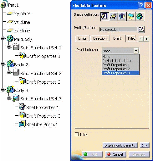
Because some sub-elements of the part can be molded in different directions, there is no limitation on the number of Draft Properties features you can define in a functional body.
-
Click the Draft Properties icon
 .
.
Note that it is not possible to set draft properties feature during the definition of a functional feature.
The Draft Properties dialog box appears.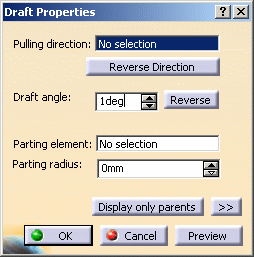
-
Select a line or a plane to define the pulling direction.
To define this type of parameter, we recommend no to use any edge supporting a functional specification.
A red arrow indicates the pulling direction in the geometry area. By clicking on this arrow, you reverse the direction.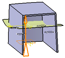
-
Enter 2deg in the Draft angle field to edit the default angle value.
-
Parting elements are optional. For the purpose of our scenario, select Extrude.1.
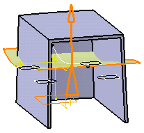
Contextual commands available from the Parting element field let you create planes. These commands are:
Create Plane: for more information, see Creating Planes.
XY Plane: the XY plane of the current coordinate system origin (0,0,0) becomes the parting element.
YZ Plane: the YZ plane of the current coordinate system origin (0,0,0) becomes the parting element.
ZX Plane: the ZX plane of the current coordinate system origin (0,0,0) becomes the parting element.
Create Join: joins surfaces or curves. See Joining Surfaces or Curves.
Create Extrapol: extrapolates surface boundaries or curves. See Extrapolating Surfaces and Extrapolating Curves.
-
Click OK to confirm the draft properties you defined.
Draft Properties.X is added to the specification tree in the Solid Functional Set.X node.
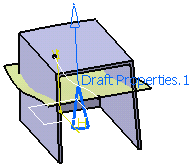
The blue graphics representation is located on the geometrical element used for defining the pulling direction, or the parting element or at the part's origin.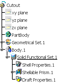
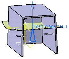
This representation is associative with the geometry so when the parting element or direction is modified, the representation is updated.
Draft Properties Versus Intrinsic to Feature
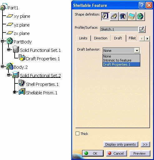
The draft properties apply to all the features of the shellable body provided that these are not assigned the Intrinsic to feature option to define their draft behaviors. If that occurs, what you need to do then is just edit the features. More precisely, click the Draft tab and change Intrinsic to feature to Draft Properties.x.
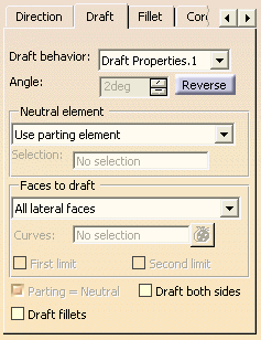 |
For more information about defining draft properties specific to a feature, refer to the Reference Information.
