The Transform feature is a type of feature modifier. This capability modifies a set of functional features of the active body by applying a transformation to them individually. The affected features retain their full functional behavior.
- The
command allows you to define four types of transformations:
 Translation - Translates one or more
features.
 Rotation - Rotates one or more features
about an axis.
 Scaling - Resizes one or more features
based on a ratio factor.
 Symmetry -
Applies a Symmetry transformation by reflection.
Symmetry -
Applies a Symmetry transformation by reflection.-
 Affinity - Transforms the absolute size by multiplying a scale ratio.
 -
 Axis to Axis - Transposes the geometry
from one reference axis system to another.
An “Axis to Axis” transformation transposes all the geometries of the selected features from one reference axis system to another. The transformation that is applied to the geometry is the delta transformation from the reference axis to the target axis.
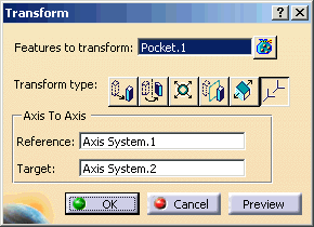
- Reference: The axis system to map the geometry from.
- Target: The axis system to map the geometry into.
Reference and Target Axes are required:
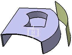
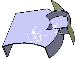
This scenario illustrates an Axis to Axis transform applied to a functional feature (Pocket).
Open the Transform.CATPart document.
 |
-
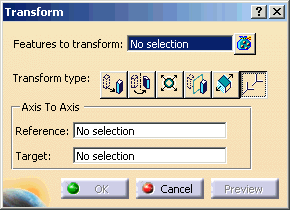
Click the Transform icon
 . The Transform
dialog box is displayed.
 Set Transform type: Axis to Axis

-
Select Features to transform: Pocket.1
-
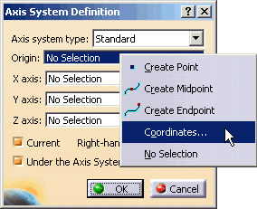
Select Reference: Create Axis System using RMB
Select Origin: Coordinates using RMB
-
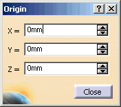
Enter X=0mm, Y=0mm, Z=0mm in Origin dialog.
-
Select X Axis: Coordinates using RMB
-
Select default for X=1mm, Y=0mm, Z=0mm in X Axis dialog.
-
Select Y Axis: Coordinates using RMB
-
Select default for X=0mm, Y=1mm, Z=0mm in Y Axis dialog.
-
Select Z Axis: Coordinates using RMB
-
Select default for X=0mm, Y=0mm, Z=1mm in Z Axis dialog.
-
Click OK in Axis System Definition dialog for Reference.
-
Select Target: Create Axis System using RMB
Select Origin: Coordinates using RMB
-
Enter X=50mm, Y=0mm, Z=0mm in Origin dialog.
-
Select X Axis: Coordinates using RMB
-
Select default for X=1mm, Y=0mm, Z=0mm in X Axis dialog.
-
Select Y Axis: Coordinates using RMB
-
Select default for X=0mm, Y=1mm, Z=0mm in Y Axis dialog.
-
Select Z Axis: Coordinates using RMB
-
Select default for X=0mm, Y=0mm, Z=1mm in Z Axis dialog.
-
Click OK in Axis System Definition dialog for Target.
-
Click OK in Transform dialog.
 |
 |
 |
 |
 |