-
Select Edit > Representations > Design Mode... to snap the shuttle on geometry (axis, points, intersection points).
-
Double-click the shuttle in the specification tree (shuttle.1).
The Edit Shuttle dialog box, the Preview window and the Manipulation pop-up toolbar appear. -
Move the shuttle (shuttle.1) as shown below.
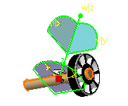
Now you need to snap the shuttle on geometry (in this case to the wheel axis), and you are going to reposition the shuttle in its initial position. -
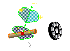
Use the Ctrl key and 3D compass manipulation handle to drag the shuttle onto the required object.
-
Release the mouse button to drop both the shuttle and compass onto the object.
The shuttle is snapped on geometry. 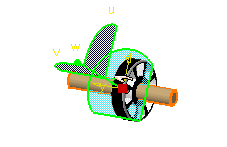
-
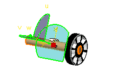
Reposition the shuttle if needed.
About Snapping Objects Using Smart Target
For example, suppose you need to reposition the screw in the hole.
If you do not work in design mode, which means you do not have the original geometry, three options are available to reposition the object (shuttle or product in track):
Case 1: Use Smart Target ![]() from the Manipulation pop-up toolbar in one shot.
from the Manipulation pop-up toolbar in one shot.
-
Double-click the shuttle or the track in the specification tree or in the geometry area.
The Manipulation pop-up toolbar is displayed. -
Click Smart Target
 .
. -
The object to be moved (shuttle, product, camera included in a shuttle or a track ) is selected
-
Point the cursor on the geometry (belonging to the to- be- moved object)
-
Click the mouse button
-
Select a second geometric element (belonging to the receiving object)
-
Click the mouse button to validate your selection
A coincidence constraint is created, the object is snapped to the desired location.
- Double-click the shuttle or the track in the specification tree or in
the geometry area.
The Manipulation pop-up toolbar is displayed.
-
Click Smart Target
. -
The first object to be moved is selected (object attached to the shuttle, product or camera included in a shuttle or a track )
-
Select a first geometric element (on the to-be-moved element)
-
Click the mouse button
-
Select a second geometric element (on the receiving element)
-
Click the mouse button
-
Select a third geometric element (on the to-be-moved element)
-
Click the mouse button
-
Select a fourth geometric element (on the receiving element)
Two coincidence constraints are created.
When you work in design mode the original geometry is
available. Smart Target![]() recognizes the geometric features (edges and faces).
recognizes the geometric features (edges and faces).