For more details, please refer to Moving the Shuttle.
-
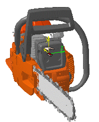
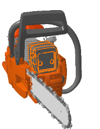
Select the required in the geometry area as shown below:
-
Click Shuttle
 .
.
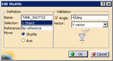
The Edit Shuttle dialog box and the Preview window appear: 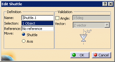
The Manipulation toolbar is also displayed: 
The shuttle graphic representation is displayed. It corresponds to the to-be-created shuttle axis. 
You can specify a maximum rotation angle around the absolute axis for the shuttle. The maximum rotation angle means the shuttle motion is defined and validated with respect to the angle value specified.
This option can be very useful to avoid liquids to spill out from specific assemblies such as a gas tank.
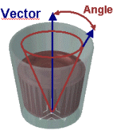
-
Select the Angle check box.
The value fields for Angle and Vector become available. -
In the Angle box, enter 45deg; in the Vector box, select the Y vector.
The Z vector is the horizontal axis. In our example, we select the Y vector, which is the vertical axis, to avoid spilling liquids. The Preview window shows selected products. 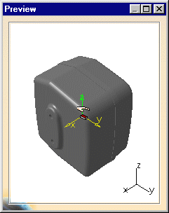
-
(Optional) Select products in the specification tree or in the geometry area to remove them from the shuttle.
-
(Optional) In the Name field, enter a meaningful name for the shuttle you want to create.
-
Click OK to end shuttle creation.
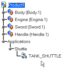
The shuttle is identified in the specification tree and in the geometry area. 