Two Path Finder ![]() modes are available:
modes are available:
- Basic mode (the default mode)
- Advanced mode for experienced users.
Open the LABYRINTH.CATProduct document.
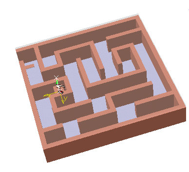
Basic Path Finder Mode
-
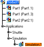
Select Simulation.1 in the specification tree.

Repositioning the shuttle axis according to a potential extraction direction eases the path finding process. -
Click Path Finder
 from the DMU Check toolbar.
A bounding box appears around the data. 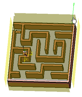

The bounding box can be used to limit the path. You can expand or shrink the bounding box by moving the cursor over the edges until you see an arrow (as shown above) and then pulling the box in the direction you wish to size it. The Path Finder dialog box is displayed: 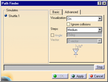

- You can also select Path Finder
 first and then select the required simulation afterwards.
- You can choose to ignore existing collisions
by selecting the Ignore collisions check box.
This is very helpful when the various assembly components are already in collision and when you do not want to take them into account when performing a path finding operation.
If this box is checked, collisions that already exist for the first shot is ignored.
If the last shot is in collision, or near collision, the results of the command may be less than ideal. If an error message appears saying No way out, users should consider altering some of the other Path Finder settings or moving the object to another position.
- You can select from among the following options:
- On (shows the object move and its various positions during calculation. You can stop the process at any time)
- Off (you are not allowed to stop the process and you do not see the progression)
- Strombo (shows positions based on a specific parameter, i.e., every 20 steps)
- Small
- Medium
- Large
- Advanced (not a step size, but required when you want to use the options in the Advanced tab).
Visualization
Steps
- You can also select Path Finder
-
Keep the default settings:
Visualization: On
Steps: Medium -
Click Apply to confirm your operation.
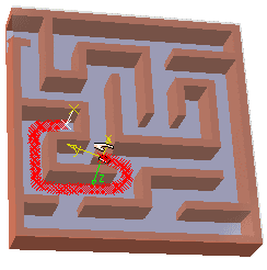
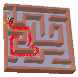
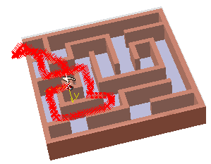
-
Click OK.
If you need to perform the smooth operation, select Tools > Options > Digital Mockup > DMU Fitting, and select the Automatic smooth check box. 
In terms of this scenario, Automatic smooth is not absolutely necessary. However, the step below is included in this procedure so that you can see how the command is used in conjunction with Path Finder  .
. -
Click Smooth
 to
smooth the path result.
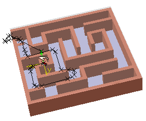
Advanced Path Finder Mode
-
On the Basic tab of the Path Finder dialog box, select Advanced from the list for Steps.
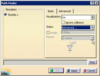
The Advanced tab appears. -
Select the required values in the Path Finder dialog box:
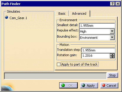
The table below provides an explanation of the fields in the Advanced tab of the dialog box. Field Possible Values Explanation Environment Smallest Detail Enter amount Accuracy used to calculate the environment description. If you enter a small value as smallest detail, the environment description will be very accurate but very costly in terms of memory size.
If you enter a big value, the description will be coarser (e.g., if the diameter of a hole is smaller than the value entered, the hole no longer exists as it is filled with matter). In this case, you gain in memory size.Repulse effect Low
Medium
HighThe higher the repulse effect, the smoother the path and the more the rotation motion is eased . Bounding box Environment Creates a bounding box around the data (default). Path Creates a box around the path only. Custom Enables you to alter the bounding box size (if you alter the size without selecting Custom, Custom is automatically selected). Motion Translation step Enter amount Unit used to define the step value in translation mode. Rotation gain Use arrows to alter amount Linked to the translation step parameter, e.g., - If rotation gain value = 2, the rotation amplitude = 2 x translation step value
- If rotation gain value = 0.5, the rotation amplitude = 0.5 x translation step value
Apply to part of the track -
When you select this check box, you will be prompted to select a beginning and end segment of the track that will define the area of the track to which you want to apply Path Finder
 .
. -
When you clear this check box (the default). Path Finder
 applies to the entire path.
-
Click Apply.
-
When done, click OK.
-
Replay the simulation.
For instance, here if you enter 30mm as Translation step value, the moving object will jump over the glass material because the path is already considered out of collision, which is not true. The following information message is displayed:
