![]()
Since
you have set up the option to enable the
external systems interfacing, an additional command
![]() is available in the Electrical Wire Routing workbench.
is available in the Electrical Wire Routing workbench.
This command allows you to select the systems to be imported.
- A geometrical bundle with bundle segments and components at their extremities
- An electrical bundle connected to the geometrical bundle
- A system.
![]()
-
Switch to the Electrical Wire Routing workbench
 .
. -
Double-click to activate the root product.
-
Click Automatic Equipotential Routing
 .
.The equipotential list opens with connectivity and attribute information: 
For the equipotentials available in the list, you get the following information: - The name
- The identifier
- The diameter
- The subtype
- If the equipotential is routed or not
- If the extremities have been found or not, or changed.
Filters can help you make your selection:
- Hide already routed equipotentials
- Hide not routed equipotentials
- Hide equipotentials which extremities are not found.
The routing options allow you to use or not the knowledge rule.
-
Select one or more equipotentials and click the right arrow.
The selected equipotentials shift to the right column: they will be routed. -
Click Route.
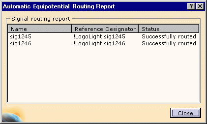
The Automatic Equipotential Routing Report is displayed: 
-
Close the report window.
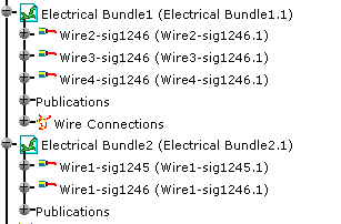
The wires are added to the specification tree: 
The bundle segments diameter are updated according to the equipotential information. SignalId attributes of generated wires are assigned the same value as the equipotential identifier (Id attribute). This lets you find the wires used to route equipotentials.
How Wires are Generated
The system queries the network to find out the shortest
path to link the signal extremities. This shortest path is computed by
taking into account separation code rules between the signals to be
routed and the already routed ones or between network and signals to be
routed. Thanks to the integration with the
knowledge language, it is possible to create design rules that mix
network rules, inter-signal rules and even more rules!
According to this path and the electrical bundle definition, the wires are
generated with their attributes in the correct bundle, and wire connections
(splice specification) are placed at forks in order to minimize the wire
length.
At the interconnection between harnesses, the wire extremity is connected to a generic pin and it is possible to refine this definition to pins using the extremity management command. Then the wires are connected according to the from-to signal specification (at the level of the pin if defined in the signal specification) by retrieving the mating connectors or pins in the harness. It can also be refined using the extremity management command.