-
Click Extremity Management
 .
.
You are prompted to select a connector or equipment. -
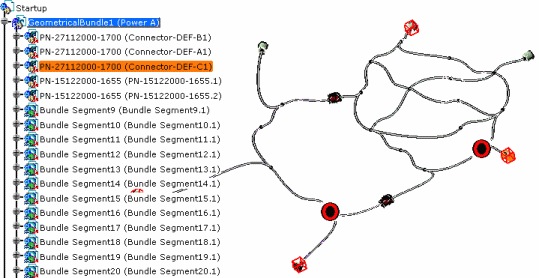
Select CONNECTOR-DEF-C1 in the specification tree or in the geometry area.
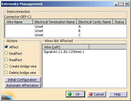
The Extremity Management dialog box opens, displaying the following information: - In the upper frame:
- The list of wires connected to each electrical termination (Termination) of the selected connector,
- In the case of a mating connector, the list of wires respectively connected to each termination of the mating connector.
- In the lower frame (Wires Not Affected):
- The wires not assigned to the selected connector.
In case of the selection of a mating connector, the dialog box looks like this: 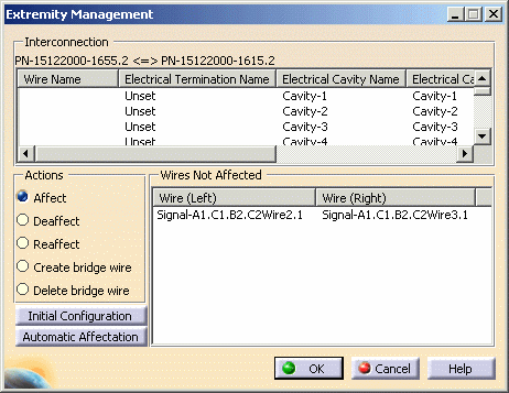

The correspondence between the cavities or terminations on each side of the mating connector is done on the IdNumber. Let's see the different options available: - Affect
- Deaffect
- Reaffect
- Create Bridge Wire
- Delete Bridge Wire

All these actions respect the signal continuity principle, that is to say that it is not possible to connect two or more wires which are not belonging to the same signal. The Affect option is selected.
- In the upper frame:
-
Select the wire in the lower frame: Wire6.1
-
Select an electrical termination/cavity in the upper frame:
The wire is assigned to the connector onto this termination. 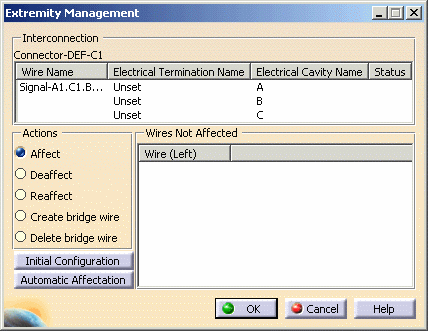
-
Select Reaffect.
-
Select the wire in the upper frame: Wire6.1
-
Select the termination/cavity on which you want to connect the wire.
The connection is modified. Note that the lower frame is disabled.
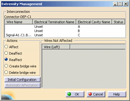
-
Select Deaffect.
-
Select the wire in the upper frame: Wire6.1
The wire is "disconnected" and moved to the lower frame. Note that the lower frame is disabled.
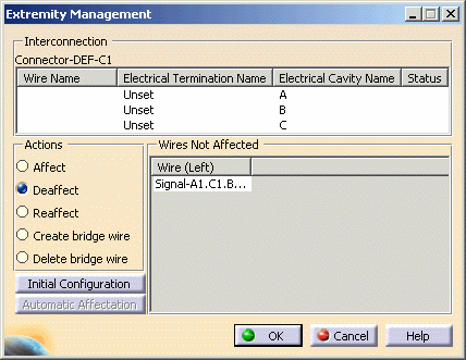
-
Select Automatic Affectation.
All the wires in the lower frame are assigned to empty cavities of the connector in the same order. Select Reaffect to modify the connection.
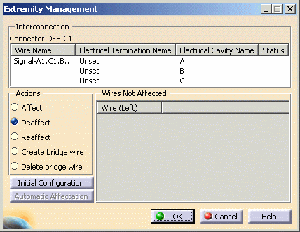
-
Select Initial Configuration to reset the dialog box.
-
Select Create bridge wire.
-
Select the two terminations you want to be linked using Ctrl key.

It is possible to create a bridge wire between two terminations already affected with wires belonging to the same signal or between a termination containing wires and an empty one. The Create Bridge Wire dialog box opens displaying a default name.

If you select a mating connector, the options let you select on which side you want the bridge wire to be created.
The dialog box looks like this: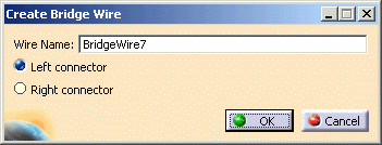
-
Change the Wire Name if need be and click OK to validate.
The bridge wire is added to the list onto the corresponding terminations. 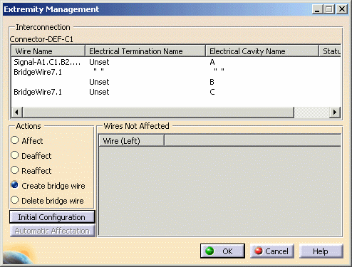
-
To delete the bridge wire, select Delete bridge wire under Actions then select BridgeWire3 in the list.
-
When you are satisfied with your choice, click OK to validate.