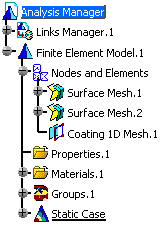
You can an XML mapping file using the Generate Mapping File contextual menu
Only available with the ELFINI Structural Analysis (EST) product.
- This command is available only if:
- There is at least one mesh part defined under the Nodes and Elements set.
- The Properties set is up-to-date. To update the property set, perform a Mesh Only computation.
- The syntax and the format of the exported XML mapping file complies with the "Extensible Markup Language (XML) 1.0 (Third Edition)"
rules as published in the World Wide Web Consortium (W3C).
For more details, refer to http://www.w3.org/TR/2004/REC-xml-20040204/. - The decimal point used in the exported XML mapping file
depends on the regional settings of your operating system (full stop or
comma). The name of the associated .xsd file also depends on the
regional settings of your operating system (PropertyMappingRules.xsd
or PropertyMappingRules-fr.xsd).
For more details, refer to Mandatory Elements of the XML Mapping File.
Open the sample27.CATAnalysis document from the samples directory.
Note that all the mesh parts are updated.
-
Right-click the Properties.1 set in the specification tree.
-
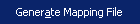
Select Generate Mapping File
 .
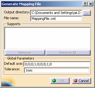
.The Generate Mapping File dialog box appears.
-
Output directory: lets you set the directory in which you will generate the XML mapping file.
-
File name: lets you specify the name of the XML file.
-
Support: lets you select mesh parts, on which you want to apply the XML mapping property.

- Multi-selection of mesh parts is available even if they are from different dimensions.
- You can select mesh parts only if they are up-to-date
To update mesh parts, perform a Mesh only computation. For more details, refer to Computing Objects Sets.
-
Remove: lets you remove the selected mesh part .
-
Remove all: lets you remove all the selected mesh parts .
-
Global Parameters: lets you set the global parameters.
-
Default Axis: lets you choose the default axis system in which the x, y and z coordinates will be interpreted.
This axis system must be orthonormal.
The three first values are the origin coordinates, the next three values are the X-axis coordinates and the last three values are the Y-axis coordinates. -
Tolerance: lets you specify the default tolerance value that will be written in the generated XML file.
Note that the units are those specified in the Tools - Options - Parameters and Measure - Units tab.
-
-
-
Select the directory in which you will generate the mapping XML file.
To do this, click the ... button and select the desired directory. -
Enter a new file name, if desired.
-
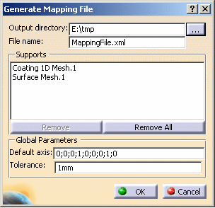
Select the desired mesh parts.
In this particular example, select the Coating 1D Mesh.1 and Surface Mesh.1 mesh parts as Support Mesh Parts.
-
Enter the axis coordinates or select the axis directly in the specification tree.
-
Enter the Tolerance value.
The Generate Mapping File dialog box appears as shown below:
-
Click OK in the Generate Mapping File dialog box.
Example with 3D solid property:
![]()
Example with 2D shell property:
![]()
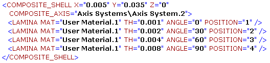
Example with 2D inhomogeneous composite property:
Example with 1D beam property:
![]()
You can now set the property characteristics (respecting the syntax rules defined in the Mapping File Syntax section) and then create a mapping property (as described in the Creating Mapping Properties section).