This task shows you how to create a mapping property.
This property allows you to apply in one shot finite element properties to
all the elements of a part (1D elements, 2D elements or 3D elements).
The identification of each element and the associated
property characteristics are listed in an XML (Extensible Markup Language)
file. This file must respect a particular syntax and format. For more
details on syntax of the mapping property file, refer to
Mapping File Syntax in this guide.
Each time the property is updated (using the Compute command)
the whole file is parsed and the properties are applied to elements.
To know more about finite element properties, refer to the Physical Properties chapter in the Finite Element Reference Guide.
Only available with the ELFINI Structural Analysis (EST) product.
- The mapping property is dedicated to analyses that are made on a part (the .CATAnalysis document must refer to a .CATPart document). In consequence, the only selectable support of the mapping property is the part on which the analysis is made. It is not possible to select a product or several parts.
- All references made in the XML file that do not belong to the .CATAnalysis document must belong to the selected part (geometries, axes).
- After applying a mapping property, any interactive
modification of a feature referenced in the XML file will not be taken
into account by the mapping property if this modification does not
invalidate the Nodes and Elements set (if the Nodes and
Elements set is invalidated, the
 symbol appears in the specification tree and the images belonging to this
set are deactivated).
This can be the case for some axes, group definitions, materials or geometrical features whose modifications do not invalidate the Nodes and Elements set.
To take into account a modification that does not invalidate the Nodes and Elements set, the mapping property must be deleted and re-created. - Creating, editing and removing mapping properties invalidate the Nodes and Elements and Groups sets.
- You cannot create several mapping properties per .CATAnalysis document.
- If other properties already exists in the Properties
set, the mapping property must be stored at the last position.
To change the order of the Properties set elements, you can use the Reorder Children contextual menu.
For more details, refer to Reordering Analysis Children. - Only analysis User Material can be referenced in the XML
file.
For more details about analysis user material, refer to Creating User Material. - Do not use the Mapping Property command to simulate a connection property.
- If there are duplicate elements in the XML file (duplicate elements
are elements that share the same nodes and belong to same mesh part and
the same group)
then the mapping property command detects only one element and ignores
the others (for instance: in case of V4 imported mesh parts). As a result only one of the duplicate
element has a property. An error message saying that some elements does not have any property appears when you launch a computation.
Open the sample27.CATAnalysis document from the samples directory.
-
Click Mapping Property
 in the Model Manager toolbar.
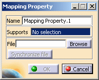
The Mapping Property dialog box appears.

- Name: lets you change the name of the property.
- Support: lets you select a part as support. The part
selection is not mandatory if the XML associated file only contains
spatial identification
(no reference to any part feature name).
For example, if the model only contain orphan meshes, you do not need to select a part. - File:
- Browse: this button lets you select the xml file
that will define the mapping property.

Reading the path you define in this dialog box is the only way to access the XML file.
If you move the CATAnalysis and the XML documents then you must modify the path of the XML file.
To do this, edit the mapping property and enter the new path of the XML file (even if the content of the XML file has not been modified).
- Browse: this button lets you select the xml file
that will define the mapping property.
- Synchronize file: this button lets you take into
account modifications you performed on a selected xml file.
After synchronizing the mapping property is no more up-to-date. You have to launch a Mesh only computation to update the property.
This button is available only if the XML associated file has been modified since the last update.
-
Select the part to be applied the property.
In this particular example, select Part.1.
-
Click Browse and select the desired xml file.
In this particular example, select the mapping01.xml file.
-
Click OK in the Mapping Property dialog box.
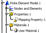
The specification tree is updated: the Mapping Property.1 feature is displayed.

-
Click Compute
 .
. -
Select the Mesh Only option and click OK in the Compute dialog box.
-
Right-click the Properties.1 set in the specification tree and select Generate Image.
-
Select the desired images.
To know more about the Image Generation dialog box, refer to Generating Images.
-
Click OK.
You can manually add and delete mapping properties.
![]()