This task shows how to create an adaptivity on a mesh part for a given static analysis case solution.
- The Adaptivity functionalities are only available with static analysis solution (without multi loads) or a combined solution that references a static analysis solution (without multi loads).
- The former adaptivity specifications (created before V5R12) can be
edited but they can not be computed with adaptativity.
If you modify these specifications and launch a computation with adaptativity, a warning message informs you that these specifications will not be taken into account. You have to create new adaptativity specifications.
Open the sample07.CATAnalysis document from the samples directory.
- Compute the solution.
To do this:
- Click Compute
 .
. - Select the All option.
- Click OK in the Compute dialog box.

For more details, refer to the Compute Objects Sets.
- Click Compute
- Optionally, you can generate an error map image to visualize the
current error.
To do this, click Precision  .
.
For more details, refer to Visualizing Precisions.

-
Click New Adaptivity Entity
 .
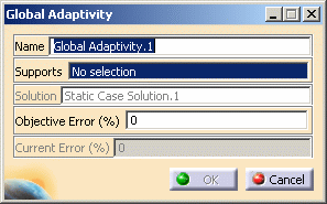
.The Global Adaptivity dialog box appears.

- Name: lets you change the name of the global adaptivity.
- Supports: lets you select the supports on which you
want to refine the mesh.

You can select as support one or several mesh part (Octree 2D or Octree 3D).
- Solution: gives you information on the
referenced solution name.

If your document contains several analysis cases, the referenced solution is the solution belonging to the current analysis case.
If you want to change the reference solution, use the Set as Current Case contextual menu. - Objective error (%): lets you specify the objective error of the selected mesh part.
- Current error (%): gives you information on the current error of the selected mesh part.
-
Select the desired mesh part.
In this particular example, select the OCTREE Tetrahedron Mesh.1: Part3 mesh part under the Nodes and Elements set.

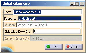
The Global Adaptivity dialog box is updated. You can now visualize the value (in %) of the current error.

-
Enter the desired Objective error (%) value.
In this particular example, enter 9 as Objective error (%) value.
-
Click OK in the Global Adaptivity dialog box.
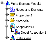
An Adaptivities.1 set is created in the specification tree containing a Global Adaptivity.1 object.

- You can edit the global adaptivity you just created.
To do this, double-click the Global Adaptivity.1 object in the specification tree. - You can create several Adaptivities objects associated to the same Static Solution and corresponding to the different mesh parts.
You can now compute the model with adaptivity (for more details, refer to Computing with Adpativity) or create local adaptivity specifications (for more details, refer to Creating Local Adpativity Specifications).
![]()