![]()
Select Tools > Options...> Equipment & Systems to set the options:
-
In the Electrical Process Interfacing tab:
- Make sure Enable External Systems Interfacing is checked.
- However, you are required to define the path of the folder in which the XML files available are stored: .../online/elbug_C2/samples/cavityinfo
-
In the Electrical Mapping tab, select the working catalog and define a mapping for the electrical objects: .../online/elbug_C2/samples/cavityinfo/ElecIntegration.catalog
For more information about the settings, refer to the Customizing section.
![]()
-
Click Select External Systems
 and select Electrical Bundle2.1:
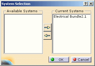
-
Click Manage Links
 .
.
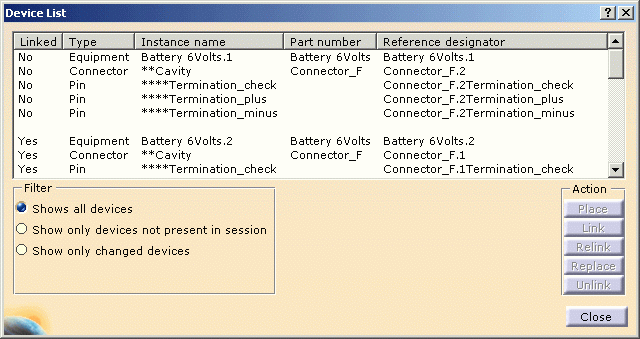
The Device List displays. -
Select the second equipment in the list and click Place.
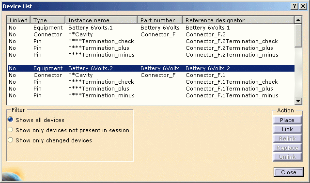
Since information is available for the selected object in the external electrical specification, the following dialog box displays at placement: 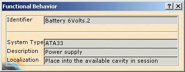
The Identifier is the reference designator of the device to be placed. System Type, Description, and Localization are textual information related to this device coming from the external electrical specification.
At the same time, the Catalog Browser opens with the correct catalog according to the options previously set up. -
Successively select the proposed equipment in the catalog, then validate the cavity in the geometry area.
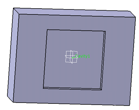
Note the cavity label showing in the geometry area. The equipment is placed and linked. 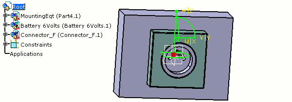
-
Click Close when you are done.