![]()
This task explains how to place electrical components from the external device list managing the cavity placement:
- Automatic creation of assembly during placement from external data
- Placing equipment in cavities of mounting equipment with label display.
This working mode is only proposed if the component to be placed has a cavity connection point. Otherwise the standard placement is performed (placement at the origin 0,0) and the step 6 is avoided.
Automatic Creation of Assembly during Placement from External Data
The automation of assembly creation is a highly productive method that lets you get the most out of placement from external data.
Hence, it is possible to describe in the external data (i.e. XML file):
- How connectors are assembled in an item of equipment
- How contacts are assembled in a single insert connector.
This description is used to automatically create:
- The assembly of connectors in the equipment cavities when the equipment is placed
- The assembly of contacts in the single insert connector cavities when the single insert connector is placed.
In order to enable this automatic assembly, there must be some mapping between the XML description and the V5 electrical references in the catalog definition.
For a connector to be correctly placed in the right cavity of an item of equipment:
- The equipment and connector PartNumber in the XML file must correspond to items in the V5 catalog.
- The equipment must have a cavity with a defined name in the V5 catalog.
- The connector name in the XML file must correspond to a cavity name
of the V5 equipment.
XML File
V5 Catalog
XML Equipment (PartNumber1)
|
|
|
-- XML Connector (Name, PartNumber2)
--> V5 Equipment (PartNumber1)
|
|-- Cavity (Name)
--> V5 Connector (PartNumber2)
Similarly for a contact to be correctly placed in the right cavity of a connector:
- The connector PartNumber in the XML file must correspond to a connector in the V5 catalog.
- Each pin PartNumber in the XML file must correspond to a contact in the V5 catalog
- The cavity name in the XML file to which a pin is connected must
correspond to a cavity name of the V5 single insert connector.
XML File
V5 Catalog
XML Connector (PartNumber1)
|
|-- XML Cavity (Name)
|
-- XML Pin (PartNumber2)
--> V5 Single Insert Connector (PartNumber1)
|
--> |-- Cavity (Name)
--> V5 Contact (PartNumber2)
![]()
-
In the Tools > Options... > Equipment & Systems > Electrical Process Interfacing tab:
-
Make sure the Enable External System Interfacing is enabled.
-
Select
...\online\cfysm_C2\samples\ElectricalManageLinksas System Repository.
-
-
In the Tools > Options... > Equipment & Systems > Electrical Mapping tab:
-
Select
...\online\cfysm_C2\samples\ElectricalManageLinks\CatalogOfDevices.catalogas Working Catalog. -
Define the mapping for the electrical objects.
-
Refer to the Customizing documentation.
![]()
-
Click Select External Systems
 .
.
Select the only system available and validate: PlaceAssemblyfromXML. -
Click Manage Links
 to display the list of the devices to be placed.
The device list displays. 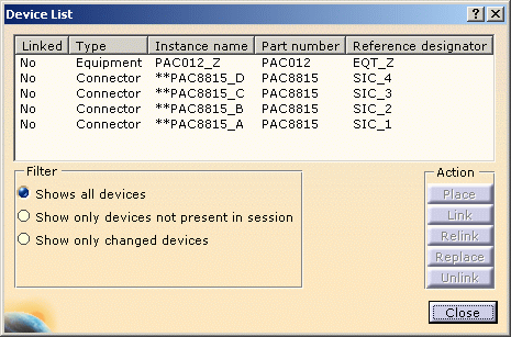
-
Select the equipment: PAC012-Z
The Place button is activated. -
Click Place.
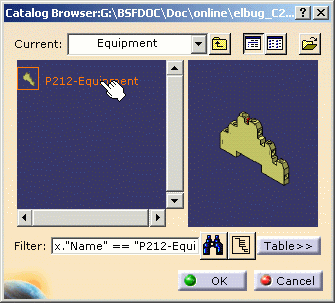
Since a mapping has been defined and the part number retrieved from the external data, the catalog browser opens with the predefined equipment: 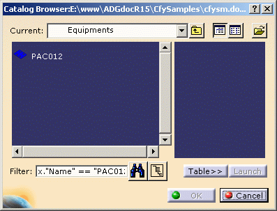


-
Select this equipment and click OK.
The catalog closes. The equipment and connectors are placed. 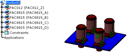
The device list is updated: the equipment and connectors now are referenced as Linked. 
-
Click Close when you are done.
Placing Equipment in Cavities of Mounting Equipment
![]()
-
In the Tools > Options... > Equipment & Systems > Electrical Process Interfacing tab:
-
Make sure the Enable External System Interfacing is enabled.
-
Select
...\online\elbug_C2\samples\managelinksas System Repository.
-
-
In the Tools > Options... > Equipment & Systems > Electrical Mapping tab:
-
Select
...\online\elbug_C2\samples\managelinks\CatalogOfDevices.catalogas Working Catalog. -
Define the mapping for the electrical objects.
-
Refer to the Customizing documentation.
![]()
-
Click Select External Systems
.
Select the only system available and validate. -
Click Manage Links
to display the list of the devices to be placed.The device list displays. 
-
Select an equipment: P212-1
The Place button is activated. -
Click the Place button.
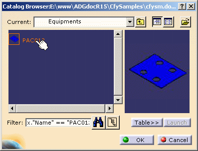
Since a mapping has been defined and the part number retrieved from the external data, the catalog browser opens with the predefined equipment: 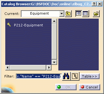
-
Select this equipment and click OK.
The catalog closes. Moving the cursor over the device displays the cavities available for placement: 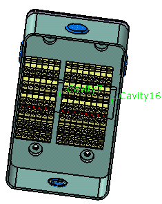
-
Click the cavity you want to use:
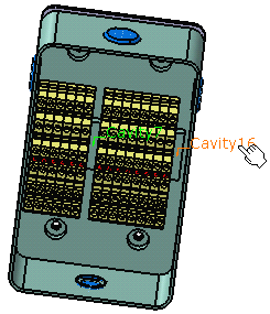
The equipment is placed. 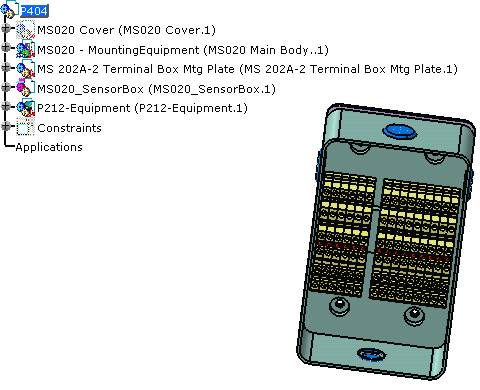
The device list is updated: the equipment is now referenced as Linked. 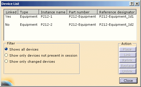
-
Repeat these steps for the second equipment:
Note that the cavity, where you have previously placed the equipment, now shows in red. It is not available for placement. 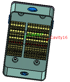
Click the last cavity available: the equipment is placed, the device list and the specification tree are updated. 
-
Click Close when you are done.